Download
1 / 24
240 likes | 434 Views
Detection of Electromagnetic Radiation II: Optics and Radiation Scattering Matrix. Phil Mauskopf, University of Rome 16 January, 2004. 1990s: SuZIE, SCUBA, NTD/composite. 1998: 300 mK NTD SiN. PLANCK: 100 mK NTD SiN. Transmission line wave equation:. I(x). V(x). V(x+dx). L. C.

E N D
Detection of Electromagnetic Radiation II:Optics and Radiation Scattering Matrix Phil Mauskopf, University of Rome 16 January, 2004
1990s: SuZIE, SCUBA, NTD/composite 1998: 300 mK NTD SiN PLANCK: 100 mK NTD SiN
Transmission line wave equation: I(x) V(x) V(x+dx) L C L dx dI(x)/dt = V(x+dx) - V(x) L dI/dt = dV/dx C dx dV(x)/dt = I(x) - I(x-dx) C dV/dt = dI/dx L d2I/dxdt = d2V/dx2 C d2V/dt2 = d2I/dxdt = (1/L) d2V/dx2 LC d2V/dt2= d2V/dx2 Same equation for current Wave solutions have property: V/I = L/C = Z of line v2 = 1/LC = speed of prop.
How to calculate inductance: 1. Apply 1 V for 1 sec to loop with area = d h B = 1/ (d h) 2. Calculate H from , B H = B/ = 1/ (d h) 3. Calculate current from path integral around loop I = Hdl No field outside, so integral is just: I = Hw = w / (d h) 4. Definition of inductance: LI = Vdt = 1 L = (d h)/w Proceedure also works if include field outside…modifies L w d I h + -
How to calculate capacitance: 1. Apply 1 A for 1 sec to plates with area = d h Develops D field, charge D = 1/(d w) 2. Calculate E from , D E = D/ = 1/(d w) 3. Calculate current from Integrate between plates to get V V = Edl = h/(d w) 4. Definition of capacitance: CV = Idt = 1 C = (d w)/h = A/h Just like we knew... w d I h
Impedance of transmission line: C = (d w)/h C = (w/h) L = (d h)/w L = (h/w) Z = L/C = L/C = (h/w) / First part depends on geometry, second on materials Therefore, we can choose the impedance of a transmission line by changing the geometry and material L Z = C
Resistive elements in transmission line - loss: R L G C R represents loss along the propagation path can be surface conductivity of waveguide or microstrip lines G represents loss due to finite conductivity between boundaries = 1/R in a uniform medium like a dielectric Z = (R+iL)/(G+iC) Z has real part and imaginary part. Imaginary part gives loss
Example - impedances of transmission lines Parallel strips - 5 m wide, 0.3 m separation, = 4.5 (SiO) Z ~ h/w * 377/ = 10 Microstrip line - one plate inifnitely wide therefore impedance is slightly lower Z ~ 5
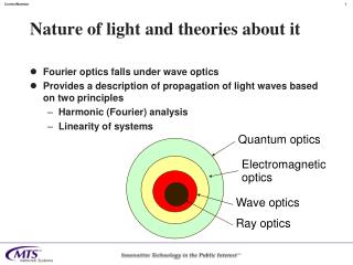
Propagation of electromagnetic radiation: Geometry of conducting boundaries and properties of material containing E, H fields (, ) determine impedance Parallel conducting plates Enclose in conducting walls - waveguide Coaxial cable Micro-strip line Coplanar waveguide Coplanar striplines Slotline etc. Given that the solution for the propagation of EM waves is different for each of the above types of boundary conditions, how do we transform a giant plane wave coming from a distant source into a wave travelling down a tiny transmission line without losing information? - Answer: optics
Dielectric materials, index of refraction, impedance mismatch: Transmission line analogy I T Z1 Z2 1 2 + - R Fields b/c: 1 + R = T Energy flow: 1 - R2= (Z1/Z2)T2 T = 2Z2/(Z1+Z2) = 2 1 /(1+ 2) = 2n1/(n1+n2) R = (Z1-Z2)/(Z1+Z2) Z1= /1 Z2= /2
Anti-reflection coating: d T1 T2 Transmission line analogy I Z1 Z2 Z3 + - R T 1 2 3 T = 4Z2Z3e-ikd/[(Z1+Z2)(Z2+Z3) + (Z2-Z1)(Z3-Z2) e-2ikd] R = (Z2-Z1)(Z3+Z2) + (Z2+Z1)(Z3-Z2)e-i2kd (Z1+Z2)(Z2+Z3) + (Z2-Z1)(Z3-Z2) e-i2kd k = 2/2 depend on d, - resonance
Anti-reflection coating: d T1 T2 Transmission line analogy I Z1 Z2 Z3 + - R T 1 2 3 Off resonance: d >> , e-ikd = 1 T = 4Z2Z3/[(Z1+Z2)(Z2+Z3) + (Z2-Z1)(Z3-Z2)] Without intermediate dielectric: T = 2Z3/(Z1+Z3)
Optics: Direct coupling to detectors (simplest) Need to match detector to free space - 377 One way to do it is with resistive absorber - e.g. thin metal film Transmission line model: Converts radiation into heat - detect with thermometer = the famous bolometer! How about other detection techniques? Impedance mismatch? - Non-destructive sampling - sample voltage - high input Z - sample current - low input Z Both cases the signal is reflected 100% E.g. JFET readout of NTD, SQUID readout of TES Z0 + - R=Z0
Optics: Direct coupling to detectors (simplest) Without an antenna connected to a microstrip line, the minimum size of an effective detector absorber is limited by diffraction Single mode - size ~ 2
Optics: Modes and occupation number A mode is defined by its throughput: A = 2 The occupation number of a mode is the number of photons in that mode per unit bandwidth For a single mode thermal source emitting a power, P in a bandwidth , with an emissivity, The occupation number is: N = (P/2h)(1/ )
Scattering matrix: Ports Ports are just points of access to an optical system. Each port has a characteristic impedance Any optical system can be described completely by specifying all of the ports and their impedances and the complex coefficients that give the coupling between each port and every other port. For an optical system with N ports, there are NxN coefficients necessary to specify the system. This NxN set of coefficients is called the Scattering Matrix
Scattering matrix: S-parameters The components of the scattering matrix are called S-parameters. S11 S12 S13 S14 ... S =
Scattering matrix: Lossless networks - unitarity condition, conservation of energy For a network with no loss, the S-matrix is unitary: SS = I This is just the expression of conservation of energy, For a two port network: 1 + R = T
Scattering matrix: Examples - two-port networks Dielectric interface: S = This is because R = (Z1-Z2)/(Z1+Z2) Going from lower to higher impedance Z1 Z2 gives the opposite sign as going from higher to lower impedance. T R -R T
Scattering matrix: Power divider How about 3-port networks? Can we make an optical element that divides the power of an electromagnetic wave in half into two output ports? Guess: What is the S-matrix for this circuit? What is the optical analogue? 2 Z1 Z1 2 Z1
Scattering matrix: 4-port networks - 90 degree hybrid A (A+iB)/2 (A-iB)/2 B 0 0 1 1 0 0 i -i 1 1 0 0 i -i 0 0 S =
Scattering matrix: 4-port networks - 180 degree hybrid A (A+B)/2 (A-B)/2 B 0 0 1 1 0 0 1 -1 1 1 0 0 1 -1 0 0 0 3 3 0 S = =
Two types of mm/submm focal plane architectures: Bare array Antenna coupled IR Filter Filter stack Bolometer array Antennas (e.g. horns) X-misson line SCUBA2 PACS SHARC2 Microstrip Filters Detectors BOLOCAM SCUBA PLANCK
Mm and submm planar antennas: Quasi-optical (require lens): Twin-slot Log periodic Coupling to waveguide (require horn): Radial probe Bow tie