Download
1 / 44
440 likes | 442 Views
Explore the evolution of modular electronics, from NIM to PCI and PCIe, and learn about future trends like serial interconnects and ATCA.

E N D
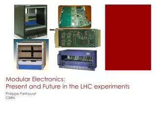
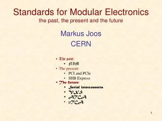
Standards for Modular Electronicsthe past, the present and the future Markus Joos CERN • The past: • NIM • The present: • PCI and PCIe • SHB Express • The future: • Serial interconnects • VXS • ATCA • MTCA
Why Modular Electronics? Why use Standards? • Benefit from 3rd party products, services and support • Competition gives you better prices and alternative suppliers • Standards make it easier to define interfaces between sub-systems • But not all standards are equally good: • Too old: poor performance, few suppliers, expensive • Too new: Interoperability issues, unclear long term support • Too exotic: Too few suppliers (sometimes just one) • As in programming a system becomes unmanageable if too much functionality is put into a single functional block • Modularizing DAQ electronics helps in these respects: • Allows for the re-use of generic modules in different applications • Limiting the complexity of individual modules increases their reliability and maintainability • You can profit from 3rd party support for common modules • Makes it easier to achieve scaleable designs • Upgrades (for performance or functionality) are less difficult • Etc.
NIM NIM crate • NIM modules (usually) • Need no software • Are not connected to a computer • Are used to implement trigger logic • These functions (any many others) are available • Discriminators • Coincidences • Amplifiers • Timers • Logic gates (and / or) • Level converters • HV power supplies • .... A small DAQ system • Initially (1964): NIM = Nuclear Instrument Modules • But it was used outside of "nuclear science" • Therefore: NIM = National Instrument Modules • But is was used outside of the USA • Therefore: NIMstands forNIM
NIM basics • 1st NIM standard: July 1964 • 1st commercial module: November 1964 • Module dimensions: 34 x 221 x 246 mm • NIM logic levels: • 0 = 0A (0V) • 1 = -12 to -32 (typical -16) mA at 50 Ω (-0.8V) • NIM connector • 42 pins in total • 11 pins used for power (+/- 6, 12, 24V) • 2 logic pins (reset & gate) • 29 pins reserved for future use since 1964 • 1983 NIM digital bus (IEEE 488 – GPIB) • Rarely used NIM connector
NIM – the next generation NIM is still very alive Some examples General purpose NIM module with programmable logic (LabView) 100 MS/s digitizer with optical read-out
PCI • First standardized in 1991 • Replaced the older ISA cards • Initially intended for PC cards • Later spin-offs: CompactPCI, PXI, PMC • Parallel PCI has almost disappeared -> replaced by serialPCIe • But there are still some ICs with parallel PCI in use on modern PCs/SBCs PCI slots PCI card PC motherboard
bussed lines Initiator & arbiter Initiator Target Target arbitration PCI basics • Main features of the original parallel protocol (not to be confused with PCIe) • Synchronous timing • But wait cycles possible • Clock rates • Initially 33 MHz. Later: 66 MHz, (PCI-X: 100 and 133 MHz) • Bus width • Initially 32 bit. Later: 64 bit • Signaling voltage • Initially 5 V. Later 3.3 V (->slot keying) • Terminology • A data transfer takes place between an INITIATOR (master) and a TARGET (slave) • Bus topology • 1 to 8 (depending on clock rate) slots per bus • Busses can be connected to form a tree • Address and data as well as most protocol lines are shared by all devices; The lines used for arbitration are connected point-to-point; The routing of the interrupt request lines is more complicated… • A system can consist of several Initiators and Targets but only one Initiator can receive interrupts
PCI basics - 2 • Address spaces • Configuration space • Standardized registers for the dynamic configuration of the H/W (plug-and play) • I/O space • For device specific registers • MEM space • General purpose space for registers and memory • Cycle types(encoded in the C/BE[3::0]# lines) • Single cycles • Read / write of all 3 address spaces • Bursts • MEM read / write (with special features for cache handling) • (Typical) performance • Single cycle: 2 (3 for read) -> ~10 clock cycles • 33 MHz / 32 bit: 66 MB/s -> ~10 MB/s • 64 MHz / 64 bit: 264 MB/s -> ~40 MB/s • Bursts: • 33 MHz / 32 bit: Max. 132 MB/s • 64 MHz / 64 bit: Max. 528 MB/s • PCI-X @ 133 MHz: 1.06 GB/s • PCI-PCI bridges add additional delays
PCI devices under Linux Show PCI tree: lspci -t -v -[0000:00]-+-00.0 Intel Corporation E7520 Memory Controller Hub +-00.1 Intel Corporation E7525/E7520 Error Reporting Registers +-01.0 Intel Corporation E7520 DMA Controller +-02.0-[0000:01-03]--+-00.0-[0000:02]----03.0 CERN/ECP/EDU Unknown device 0144 | +-00.1 Intel Corporation 6700/6702PXH I/OxAPIC Interrupt Controller A | +-00.2-[0000:03]----01.0 CERN/ECP/EDU Unknown device 0144 | \-00.3 Intel Corporation 6700PXH I/OxAPIC Interrupt Controller B +-04.0-[0000:04]----00.0 Broadcom Corporation NetXtreme BCM5721 Gigabit Ethernet PCI Express +-05.0-[0000:05]----00.0 Broadcom Corporation NetXtreme BCM5721 Gigabit Ethernet PCI Express +-06.0-[0000:06-08]----00.0-[0000:07-08]--+-04.0 Broadcom Corporation NetXtreme BCM5714 Gigabit Ethernet | +-04.1 Broadcom Corporation NetXtreme BCM5714 Gigabit Ethernet | \-08.0-[0000:08]--+-06.0 Broadcom Corporation NetXtreme BCM5704 Gigabit Ethernet | \-06.1 Broadcom Corporation NetXtreme BCM5704 Gigabit Ethernet +-07.0-[0000:09-0b]--+-00.0-[0000:0a]----02.0 CERN/ECP/EDU Unknown device 0144 | +-00.1 Intel Corporation 6700/6702PXH I/OxAPIC Interrupt Controller A | +-00.2-[0000:0b]----01.0 CERN/ECP/EDU Unknown device 0144 | \-00.3 Intel Corporation 6700PXH I/OxAPIC Interrupt Controller B +-1d.0 Intel Corporation 82801EB/ER (ICH5/ICH5R) USB UHCI Controller #1 +-1d.1 Intel Corporation 82801EB/ER (ICH5/ICH5R) USB UHCI Controller #2 +-1d.2 Intel Corporation 82801EB/ER (ICH5/ICH5R) USB UHCI Controller #3 +-1d.3 Intel Corporation 82801EB/ER (ICH5/ICH5R) USB UHCI Controller #4 +-1d.7 Intel Corporation 82801EB/ER (ICH5/ICH5R) USB2 EHCI Controller +-1e.0-[0000:0c]----01.0 ATI Technologies Inc Rage XL +-1f.0 Intel Corporation 82801EB/ER (ICH5/ICH5R) LPC Interface Bridge \-1f.3 Intel Corporation 82801EB/ER (ICH5/ICH5R) SMBus Controller The command “lspci” displays information about the PCI devices of a computer Show device details: lspci -v -s 02:03.0 02:03.0 Co-processor: CERN/ECP/EDU Unknown device 0144 (rev ac) Subsystem: Unknown device 2151:1087 Flags: bus master, 66MHz, medium devsel, latency 32, IRQ 209 Memory at d7200000 (32-bit, non-prefetchable) [size=512] I/O ports at 2000 [size=256] Memory at d8000000 (32-bit, non-prefetchable) [size=16M] Capabilities: <access denied>
Address Parallel PCI protocol Example: Single cycle read CLOCK 9 1 FRAME# 6 A/D Data 2 4 C/BE# BUS CMD BE#’s 10 3 IRDY# 7 TRDY# 8 5 DEVSEL# Data phase Address phase • The Target does not yet drive TRDY (it may need time to prepare the data) but asks the Initiator to wait • The Target has the data ready on the AD lines. The Initiator fetches the data in the same clock cycle • By de-asserting FRAME the Initiator tells to the Target that it does not want additional data after the next data word • The cycle is over and the protocol lines get released • Assertion of FRAME starts cycle • Initiator puts address and command (cycle type) on the bus • The Initiator signals that it is ready to receive data • The initiator uses the C/BE lines to define which bytes it wants to read • Target looks at the Address and drives DEVSEL if it was addressed. If no target drives DEVSEL after at most 6 clock the Initiator will abort the cycle • The ownership of the AD lines changes from Initiator to target (only for read cycles). This requires one clock cycle Color code: Initiator – Target - shared “#” indicates active low signals
Some examples of Parallel PCI H/W 32 bit slot with 5V key 64bit slot with 3.3V key 6U CompactPCI chassis and card PC motherboard with PCI slots PXI system PMC card and carrier (VMEbus)
CompactPCI (and friends) • Special features • Based on the PCI(e) protocol • Many derivatives: CompactPCI Serial, CompactPCIPlusIO, PXI, CompactPCI Express • S/W compatibility in PCI->PCIe migration • Single master (scalability) CompactPCI crate • Why was / is it partiallysuccessful? • No large performance advantage over (well established) VMEbus • Too late to market • Many modules for Test & Measurement (PXI) PXI system
Parallel bus -> Serial link Parallel Buses Are Dead! (RT magazine, 2006) What is wrong about “parallel”? • You need lots of pins on the chips and wires on the PCBs • The skew between lines limits the maximum speed What is wrong about “bus”? • Speed is a function of the length (impedance) of the lines • Communication is limited to one master/slave pair at a time (no scalability) • The handshake may slow down the maximum speed All parallel buses are dead. All? No! • VMEbus is still used (military / research) • There is lots of PCI legacy equipment What next? • Switched serial interconnects serial link
Dev. Dev. Dev. Dev. Dev. Dev. Switch Dev. Dev. Mesh Star (Switched) serial links • Standards (just the most important) • PCIe • 1 / 10 GB Ethernet • Serial RapidIO • Infiniband • Serial ATA • FiberChannel • ……. • Commonalities • Signal rate: 2.5 – 10 GHz • Packet switching • Topology • Star: Devices connect to a fabric switch • Dual Star: Devices connect to two fabric switches (for redundancy) • Mesh: All devices have direct links to all others • Differences • Support for interrupts • Support for programmed I/O • Quality of service (guaranteed bandwidth)
Infiniband • Developed by Compaq, IBM, Hewlett-Packard, Intel, Microsoft and Sun from 1999 onwards • Characteristics • Bi-directional serial link • Aggregation of links (4x, 12x possible) • Link speed: 2.5, 5, 10 GHz • Special features • Data transfer performed without involvement of OS (latency < 2 μs) • Remote DMA (fetch data from the memory of a remote system) • Main field of application • Server and storage interconnect for high performance computing • Relevance for DAQ • Limited for a lack of DAQ F/E products • Used by CMS for the HLT N/W Serial Rapid I/O • Developed by Mercury Computer Systems and Motorola from 1997 onwards • Characteristics • Bi-directional serial link • Aggregation of links (2x, 4x, 8x, 16x possible) • Link speed: 1.25, 2.5, 3.125, 5, 6.25 GHz • Special features • Quality of Service (transfer requests can be prioritized) • Multicast • Main field of application • Chip/chip and board/board communication • Relevance for DAQ • Limited for a lack of DAQ products but some AMC/ATCA products
PCIe (aka PCI Express) • Not a bus any more but a point-to-point link • Data not transferred on parallel lines but on one or several serial lanes • Lane: One pair of LVDS lines per direction • Clock rate: 2.5 GHz (PCIe2.0: 5 GHz, PCIe 3.0: 8 GHz, PCIe 4.0: 16 GHz) • 8b/10b encoding (PCIe3.0 & 4.0: 128/130b encoding) • 250 MB/s (PCIe 1.0) raw transfer rate per lane • Devices can support up to 32 lanes • Protocol at the link layer has nothing to do with protocol of parallel PCI • Fully transparent at the S/W layer ATLAS FLX-712
PCIe performance Sequence 2 bytes Payload 0 - 4096 bytes ECRC 4 bytes LCRC 4 bytes End 1 byte Header 12 or 16 bytes Start 1 byte • Data is transferred in frames: • Note: • H/W may limit max payload size (typically 128, 256 or 512 bytes) • Every data packet has to be acknowledged (additional overhead) • Read transactions may cause additional delays • The actual performance may be as low as ~15% of the theoretical maximum • Achieving more than ~80% link efficiency is difficult • The topology of the system (PC motherboard) matters as well • You may have to use process / tread affinity in order to tie your I/O code to the CPU that connects directly to your I/O cards QPI* PCI slot 3 PCI slot 1 CPU 1 CPU 2 PCI slot 4 PCI slot 2 * Intel QuickPath Interconnect
PCIe applications Lately PCIe cards have become trendy • The server that hosts them provides: • Power, cooling, mechanical enclosure • Computing power Examples (custom designs): • BNL FLX-712: 48 optical channels (10 Gbps) • Used by ATLAS for new read-out (will replace some VME systems) • Used by protoDUNE • Under discussion for sPhenix • LHCb PCIe40 • Also used by ALICE and Mu3E(PSI) Limitations: • Space for I/O (front panel) • PCB size (two large FPGAs won’t fit) • Cooling capacity LHCb PCIe40
PICMG 1.3 – The basic idea • A desk-top PC has at most 7 slots for PCI(e) cards • PC motherboards are quickly getting obsolete • Let’s design a standard that is more adapted for using PCI cards in an industrial domain • Modularize system by decupling computing core from PCI card backplane
PICMG 1.3 – SHB Express The SHB • Two (A & B) or 4 (A, B, C & D) connectors • Connector A: PCIe • (1 x16) or (2 x8) or (1 x8 + 2 x4) or (4 x4) • Connector B: PCIe • (1 x4) or (4 x1) • Connector C: • Additional I/O • Connector D: • 1 32bit PCI(-X) • SHBExpress = System Host Board standard for PCIe • Standardized in 2005 • Defined in the standard • SHB board mechanics (two board formats) • PCI(e) interface between SHB and backplane • Additional I/O (SATA, USB, Ethernet, etc.) that may be routed to the backplane • Backplane design rules • Systems consist of: • One SHB • One backplane • One or several PCIe, PCI-X or PCI cards D C B A
SHB – the backplanes The backplane has to match the PCIe configuration of the SHB • x16 on connector A: graphics class • 2 x8 on Connector A: server class • Relevance for DAQ: • For small systems • For re-use of old PCI cards Segmented backplane with 4 SHB and 12 PCIe slots for a 19” 4U chassis SHB slot PCIe slots PCI(-X) slots PCIe switch PCI bridge A complete 4U system
The next generation What new standards are available? • VITA41: VXS • PICMG 3.x: ATCA (Advanced Telecommunications Computing Architecture) • PICMG MTCA.x: MicroTCA/µTCA • PICMG AMC.x: Advanced Mezzanine Card (for ATCA and µTCA) Not covered in this talk: • VITA46: VPX • PICMG 2.x: Compact PCI (cPCI) • PICMG EXP.0: PCIe for cPCI • PCIMG CPCI-S.0: CompactPCI serial • PICMG ATCA300.0: ATCA for 300mm deep systems (no rear I/O) • And many more…
VXS – The basic idea • VMEbus mechanics is no so bad: • Let’s keep it • There is a lot of legacy equipment: • Let’s re-use it • The data transfer bandwidth could be better: • Let’s add an optional high-speed communication channel
VXS - Components VXS Backplane VMEbus crate Switch card Payload card
VXS (VITA 41, ~100 pages) • Essentially 6U (but 9U not excluded) VMEbus with a new P0 connector • Two types of cards • Payload • Switch (one card required, second for redundancy) • Network topology: (dual) star • Connectivity for payload cards • 16 differential pairs (10 GHz) defined by the standard (and routed to switch cards) • 31 reserved pins available on P0 • Sub-standards • 41.1: Infiniband • 41.2: Serial RapidIO • 41.3: IEEE Std 802.3 (1000 Mb/s Ethernet) • 41.4: PCIe • Hot Swap: According to VITA 1.4 • System management based on I2C / IPMI but only formulated as recommendation VXS connector Switch card • Why was / is it NOT successful? • Had to compete with xTCA • Did not address many shortcomings of VMEbus • Power, cooling, management, hot swap, module width • Little market interest • Backwards compatibility not necessarily an advantage Backplane
Advanced TCA – the basic idea • Telecom companies are using proprietary electronics: • Let’s design a standard for them from scratch • It has to have all the features telecom companies need: • High availability (99.999%) • Redundancy at all levels • Very high data throughput • Sophisticated remote monitoring and control
Advanced TCA - Components Shelves Shelf manager(s) Payload card Switch blade Backplane AMC carrier Rear Transition Module Hot-swap fans
Advanced TCA (650 pages + IPMI) Relevance for DAQ: Very trendy! (and very complex) Replaces 9U VME • More of a system than a board standard • Started in 2001 by ~100 companies • One form factor • Front: 8U x 280 mm x 30.48 mm (14 slots per 19” crate) • Rear: 8U x 60 mm (5W) • Supply voltage: -48 V (-> DC-DC conversion each on-board) • Power limit: 200 W (400-600-800 W) per card • Connectors • Zone 1: One connector for power & system management • Zone 2: One to five ZD connectors for data transfer • Zone 3: User defined connector for rear I/O • Connectivity • Up to 200 differential pairs • 4 groups • 64 pairs for Base Interface (usually Eth., star topology) • 120 pairs for Fabric Interface (star or full mesh) • Ethernet, PCIe, Infiniband, serial RapidIO, StarFabric • 6 pairs for Clock Synchronization • 10 pairs for Update Channel • System management based on IPMI, I2C and FRU data ATCA signal connector Zone3 Zone2 Zone1 ATCA board
ATCA HA features (applies also largely to μTCA) Redundancy • Power Supply modules • Ventilators • Shelf managers • Switch blades Electronic Keying • Based on FRU information payload cards may be accepted / rejected in a given slot Hot swap • Payload board will only receive (payload) power if the shelf manager can guaranty for the availability of the required resources (power, cooling, signal connections) Monitoring • Low level: IPMI on I2C • High level: SNMP (Simple Network Management Protocol) and other protocols on top of TCP/IP • System event logs Cooling • Dynamically controlled fans and several alarm levels Dedicated tree for control and monitoring
ATCA – An example • The ATLAS L1Topo board • 2 Xilinx Virtex7 XC7V690T FPGAs for data processing • 1 Kintex7 FPGA for control and data transmission • 22 layers PCB • Processes 1 Tb/s with a latency budget of 150 ns
AMC – The basic idea • ATCA blades are big. Small mezzanine modules could be helpful to modularize their functionality • PMC/XMC mezzanines are not hot-swappable • Let’s design a new type of mezzanine for ATCA
AMC • Originally intended as hot-swappable mezzanine standard for ATCA but soon used as the basis for the μTCA standard • 6 form factors: • 74 or 149 mm wide • 13, 18 or 28 mm high • 180 mm deep • Power supply: 80W (max) on +12V (and 0.5W on 3.3V management power) • Connector: 85 pin (single sided) or 170 pin (double sided) edge connector • Connectivity • Up to 12.5 Gb/s • 20+20 LVDS signal pairs for data transfer (Eth, PCIe, SAS/SATA, Serial RapidIO) • Clock interface, JTAG • Managed via local microcontroller (MMC) • IPMI messages on I2C
μTCA / MTCA – The basic idea • AMC mezzanines are great but ATCA is a heavy standard and the H/W is expensive • Let’s define a standard that allows for using AMCs directly in a shelf (i.e. Promote the AMC from “mezzanine” to “module”)
μTCA / MTCA- Components MCH Shelves AMCs
Relevance for DAQ: Very trendy! (watch out for interoperability issues) Replaces 6U VME μTCA • A system standard based on the AMC, standardized in 2006 • Min. signaling speed: 3.125 GHz • Connectivity: • 4 AMC LVDS pairs defined as “Common Options” (2 Eth. & 2 SAS ports) and connect to 1 or 2 MCH boards which provide the switching • 8 AMC LVDS pairs defined as (extended) fat pipes (1 or 10 G Eth, PCIe, RapidI/O). Connection to MCH not standardized • Remaining 8 LVDS pairs not defined (can be used for rear I/O (but rear I/O not foreseen in uTCA standard)) • System management based on IPMI / I2C • Hot-swap support for PSU & cooling • Redundant MCH (μTCA Controller Hub) • The MCH connector supports up to 84 differential pairs. Therefore only 7 pairs per AMC (based on a 12-slot backplane) can be routed to the switch.
μTCA – An example • The CMS MP7 AMC • A generic stream-processing engine • Main workhorse for the calorimeter trigger • One Virtex-7 (XC7VX690T) FPGA • 144 differential pairs running at 10 Gb/s • 72 Rx, 72 Tx • To date, the MP7s of CMS have transferred in excess of an Exabit of data without an observed error, giving a limit on the per-board bit-error rate of approximately 3 * 10-17. • Lessons learned: • Power budget (80W) at the limit • Density very (too?) high • CMS now looking into ATCA
xTCA degrees of freedom (not necessarily a complete list) • ATCA • Communication protocol(s) on the fabric channels • Routing of the fabric channels on the backplane (network topology) • Connection between front board and RTM • Degree of redundancy • Power supply at shelf level (230 VAC or -48 VDC) • AMC • Card height (13, 18 & 28 mm) • Card width (74 & 149 mm) • Communication protocols (currently 4 options) • Number of pins on the connector (85 or 170) • JTAG support • uTCA • AMC height & width • Degree of redundancy (MCH, PSU, cooling) • Routing of the fabric channels on the backplane (custom backplanes) • JTAG support • Connectivity of MCH to backplane (1 to 4 tongues) and type of communication protocol on the fat pipes • Rear transition modules (MTCA.4)
xTCA issues • The operation of an xTCA system requires a complex, standard compliant S/W infrastructure • Efforts to provide open source management S/W for xTCA: OpenSAF, SAForum • As many features of the standard(s) are optional, products from different vendors may not be compatible • Efforts to insure interoperability of xTCA products: CP-TA, SCOPE alliance • Interoperability workshops • Sub-standards for use in “physics” • ATCA 3.8: Standardizes RTMs and clock signals • MTCA.4: Adds RTMs (and other features) to MTCA. AMCs communicate via PCIe • The market does not yet provide lots of front end modules for physics DAQ • See: http://mtca.desy.de/ • There is little information available about the system performance (end to end H/W performance and S/W overhead) of the data transfer links • This makes it difficult to dimension a DAQ system
Mezzanines PMC FMC XMC A “module” is not necessarily monolithic. Often it carries mezzanines Use mezzanines to: • Improve maintainability (mezzanines are easy to replace) • Implement general purpose functions (e.g. controller, ADC, DC/DC) • Some popular mezzanine standards • PMC (IEEE P1386.1) • Relatively old PCI based standards for VMEbus, CompactPCI, etc. • XMC (VITA 42) • PMC with additional high speed interface (e.g. PCIe) • FMC (VITA 57) • Small mezzanine for FPGA based designs • Heavily used (not only) on MTCA
Complexity is increasing(but how can we measure that?) By the number of pages of the standard? By the number (sub)-standard documents? Complexity leads to interoperability issues and long development cycles Note: Only the base documents are listed Sub-standards increase the volume further. Standards for the communication protocols (PCI, Eth, etc.) are also not counted
How much xTCA for the upgrade of the LHC Experiments? • All experiments have looked at xTCA for various upgrade projects and took different roads…. • ALICE: No xTCA (but PCIe cards in servers and still VMEbus) • ATLAS: ATCA • CMS: MTCA (and later also ATCA) • LHCb: No xTCA (but PCIe cards in servers) xTCA features in they eyes of the LHC experiments:
Science fiction • PICMG has announced GEN4 in 2014 • http://www.picmg.org/gen4-new-high-performance-platform/ • System throughput (to hundreds of terabits/s), module bandwidth (to tens of terabits/s), and storage capacity in exabytes. • Module cooling capacity (over 2000 Watts, with fluid cooling options) • Not H/W compatible with ATCA • What I read in my crystal ball: • Don’t expect H/W before 2020++ (now progress update since 2014) • Try not to be an early adopter • Optical backplanes • Not a new idea • Already exist for niche applications • Very expensive • What I read in my crystal ball: • Will come but not anytime soon • Servers • Data processing may shift from FPGA to CPU (or hybrids) • Networks will play a more important role • Servers with custom PCIe I/O cards may become (more) attractive • No longer science fiction for LHCb and ALICE
So, what is the right standard for me? • This obviously depends on your requirements • Bandwidth & latency • Availability of commercial products (front end) • Existing infrastructure (S/W and H/W) and expertise in your experiment • Start and duration of the experiment • Scalability requirements • Trends in HEP • LHC & experiments @ CERN: Still VMEbus & PCI based • CMS: Several μTCA systems in operation, ATCA coming • ATLAS: ATCA as VMEbus replacement, many R&D and completed projects • LHCb and ALICE: first favored ATCA then decided to go for PCs • Beam control: μTCA for (non LHC) machine control • Control systems of new accelerators: μTCA everywhere • XFEL @ DESY: 250 systems • FAIR @ GSI, ESS, MYRRHA, Wendelstein 7-X, KEK, J-PARC, IHEP, etc.
Resources • Think “open” • Open H/W: • https://www.ohwr.org/ • Open cores: • https://opencores.org/ • https://oliscience.nl/ • Standards organizations: • PICMG: www.picmg.org • PCI-SIG: www.pcisig.com • VITA: www.vita.com