Download
1 / 76
780 likes | 1.03k Views
Carrier Ethernet Technology and Standards Update. Presented by: Rick Gregory Senior Systems Consulting Engineer May 25,2011. Carrier Ethernet: Evolution, Defined. Ethernet Evolution Timeline 1970s to today.

E N D
Carrier Ethernet Technology and Standards Update Presented by: Rick Gregory Senior Systems Consulting Engineer May 25,2011
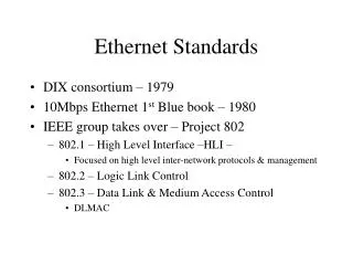
Ethernet Evolution Timeline1970s to today 1973 Metcalfe & Boggs of Xerox PARC invented ALOHA packet-based network access protocol over a wired shared medium • 3 Mb/s operation 1982 “The Ethernet Blue Book” Digital, Intel, Xerox (DIX) • 10Mb/s operation based on the Xerox PARC concepts 1985 IEEE 802.3 Carrier Sense Multiple Access w/ Collision Detection (CSMA/CD) • Formal standards definition, based on “Blue Book” 1999 Gigabit Ethernet standards ratified for use over copper twisted pair; vendors also implement fiber optic versions; 1000Base-T • IEEE 802.3ab 2000’s Fiber standards ratified for single and multimode fiber; speeds evolve to 10, 40 and (eventually) 100Gbps
Ethernet Evolution EventsEffect: Carrier Ethernet becomes Leading Transport Technology Ethernet over any media…any service over Ethernet
Forwarding Table Address Port A BCDE F 1 2 2 3 3 3 Basic Ethernet Bridging (IEEE 802.1D) Unknown DestinationMulticastBroadcast A switch builds forwarding table by LEARNING where each station is (relative to itself) by watching the SA of packets it receives. Four Important Concepts/Operations (upon switch receipt of a packet): LEARNING: The Source MAC Address (SA) and port number, if not known FORWARDING: Looking up Destination Address (DA) in table and sending to correct port FILTERING: Discarding packets if destination port = receiving port FLOODING: Sending to all other ports if DA is unknown, multicast or broadcast
Ethernet’s Evolution Originally Now Bandwidth 10 Mbps, then 100M 1 Gbps, 10G, 40G, 100G Transmission Half Duplex Full Duplex Collisions Yes (CSMA/CD) No Collisions (Full Duplex) Broadcast Domain Entire LAN VLAN Controlled Prioritization None 802.1p Topology E-LAN, E-Tree, E-Line(Access, Trunks) Bus Cabling Coax UTP, Optical (Access, Trunks) Less Than 30%Due to Collisions Approaching 100% Utilization Distance Limited by CSMA/CDPropagation Time Limited Only byMedia Characteristics
Scaling Ethernet…beyond 802.1ad (Q-in-Q) Preferred: “Large” number of customers Reality: One MAC domain for customer and Provider results in large forwarding table size 48-bit MAC address (no ‘prefixing’ as in IP address) Every network switch needs to learn Destination Address (DA) of customer switches Preferred: Customer Isolation/Transparency Reality: One L2 broadcast domain for customer and provider Broadcast storms in one customer’s network can affect other customers and provider as well Preferred: Million+ service instances Reality: Limited VLAN space, i.e., only 4095 (i.e., 212-1) 802.1ad (Q-in-Q) suggested 16million+ instances but forwarding only to same S-tag (4095!) Preferred: Deterministic behavior for services Reality: “p” bit for priority but no bandwidth guarantee & arbitrary forwarding/backup paths Data plane dependent on address table, vlan partition, spanning tree, bandwidth contention
Ethernet Transport at Layer 2 & 2.5: Approaches to COE VLAN and Stacked VLAN (Q-in-Q) Cross-Connects Explicit forwarding paths using VLAN based classification. Tunneling via VLAN tag encapsulations and translations. Defined in IEEE 802.1Q and IEEE 802.1ad specifications. Standards completed. Provider Backbone Bridging (PBB-TE) and Provider Backbone Bridging (PBB) Explicitly forwarding paths using MAC + VLAN tag. Tunneling via MAC-in-MAC encapsulations. Defined in IEEE 802.1Qay and IEEE 802.1ah specifications. Standards completed. E-SPRing Shared Ethernet Ring Topology based Protocol mechanism that delivers sub-50ms in IEEE 802.1Q and IEEE 802.1ad (Q-inQ) Ethernet Networks. Defined in ITU G.8032 specification. Standards completed. MPLS & VPLS/H-VPLS Widely deployed in the core, less so in the metro / access. Uses pseudo wire emulation edge-to-edge (PWE3) for Ethernet and multi-service tunneling over IP/MPLS. Can be point-to-point or multi-point (VPLS). Defined in IETF RFC 4364 (formerly 2547bis) and Dry Martini (IETF RFC 2026). Standards completed. Provider Link State Bridging (PLSB) Adds a SPB (Shortest Path Bridging) using IS-IS for loop suppression to make Ethernet fit for a distributed mesh and point to multi-point routing system. PBB-TE/PBB along with PLSB can operate side-by-side in the same network infrastructure. PLSB is optimized for Any to Any E-LAN and Point to Multi-Point E-Tree Network Topology Service delivery. Defined in IEEE 802.1aq specification. Standards to be completed. Target completion approximately 2H 2011. MPLS-TP Formerly know as T-MPLS (defined by ITU-T). New working group formed in IETF now called MPLS-TP. Transport-centric version of MPLS for carrying Ethernet services based on PWE3 and LSP constructs. Defined in IETF RFC 5654. Standard to be completed. Target completion approximately 1H 2012.
What’s Next in Carrier Ethernet ? 802.1aq PLSB Robust L2 Control Plane Ethernet Shared Ring Resiliency G.8032 802.1Qay PBB-TE Traffic Engineered Ethernet Tunnels Y.1731 Performance Management Proactive Performance Management 802.1ag Fault Management Service and Infrastructure CFM Diagnostics Scalable, Secure Dataplane 802.1ah PBB Ethernet has steadily evolved to address more robust networking infrastructures
CESD Technology and MechanismsOAM And QOSEthernet Service Monitoring March 2010
Design Predictable ResilienceCreate a stable network, that remains stable as it scales • Ciena is the leader in Connection-oriented Ethernet (COE) and provides a range of carrier-class resiliency schemes (RSTP, MPLS, PBB-TE) • COE tunnels (PBB-TE, MPLS-TP (future)) are connection-oriented and traffic engineered • Provides deterministic performance for predicable SLAs • Better resiliency & stability of provider networks PBB-TE domain supporting sub-50 ms protection (via 802.1ag Connectivity Check Messages) 802.1Q/ad domains protected using 802.1w RSTP with 50 ms restoration
Design Granular Bandwidth ControlControlled & measurable for predictable QoS Voice VLAN CIR/EIR MAC DA B • Specific service identification with rich L1-L2 classification • Segmented bandwidth via a hierarchy of “virtual ports” • Flexible priority resolution for CoS mapping • Traffic profiles and traffic management at all levels in the hierarchy • Specify CIR/CBS, EIR/EBS, Color Aware profiles • Allows efficient service upgrades 20/0 50/100 L2VPN 10/100 80/200 20/100 IP SA 192.168.1.23 MAC SA A 30/100 DENY TCP port 80 10/40 20/55 Flow Interface (e.g. Combo of TCP/UDP port, IP DSCP, MAC, etc.) Sub-Port (e.g. Dept VLAN range) Logical Port (e.g. all the client ports of a Business) Enhance revenue with Service Stratification
Operate Comprehensive OAMReduce the cost to run the network and keep services profitable Complete standards-based Operations, Administration, and Maintenance (OAM) offering provides visibility, manageability, and controls • Proactive SLA assurance, rapid fault isolation and minimized downtime • Includes L2 and L3 based performance measurement capability as a way to differentiate services Layer 3 SLA Monitoring & Metrics: Delay, Jitter IETF RFC 5357 TWAMP Two-Way Active Measurement Protocol Layer 2 SLA Monitoring & Metrics: Delay, Jitter, Frame Loss ITU-T Y.1731 Ethernet OAM Service Heartbeats, End-to-End & Hop-by-Hop fault detection IEEE 802.1ag CFM Connectivity Fault Management Enhanced troubleshooting, rapid network discovery IEEE 802.3ah EFM Physical Link
Technology Options for Packet Transport Routing, i.e., forward IP packets IP -over- {IPsec, GRE -over-} MPLS IP -over- {IPsec, GRE -over-} IP MPLS -over- L2TPv3 -over- IP Ethernet -over- L2TPv3 -over- IP Bridging, i.e., forward Ethernet frames based on MAC DA Ethernet -over- Ethernet: PBB Ethernet -over- MPLS: VPWS & VPLS Switching, i.e., forward of Ethernet frames based on tunnel label Ethernet -over- Ethernet: PBB-TE Ethernet -over- MPLS-TP Subscriber Management Packet transport IP/MPLS Service Edge & Core “Application” “Service” Management Metro access & aggregation MPLS (L3) IP PBB MPLS (L2) PBB-TE MPLS-TP Goal: cost-effective, high-performance transport
IEEE 802.1Qay Ethernet Tunneling • Deterministic Service Delivery • QoS & Traffic Engineering • Resiliency & Restoration • Connectivity / Service Checks • ITU Y.1731 Performance Metrics • Complete Fault Management • 802.1ag • IEEE 802.1ah PBB • (MAC in MAC) • Secure Customer Separation • Service/Tunnel Hierarchy • Reduced Network State Mechanisms to Build the Carrier Grade Enterprise Ethernet Network PBB PBB-TE Ethernet OAM
Performance Monitoring and Connectivity Fault Management
Maturing Ethernet OAM into a Transport Technology True Ethernet transport must maintain important functions from the TDM Transport Environment A Partial List of Completed and Evolving Standards Fault Management Functions Y.1731 802.1ag CCM Continuity Check P P • Traffic Engineering for deterministic bandwidth utilization • Network planning: Bandwidth resources & traffic placement • Performance monitoring & statistics collection • Fault sectionalization & propagation mechanisms • Trace & loopback facilities • Local Link Management • Control plane for automated end-to-end provisioning and resiliency LBM/LRM Loopback P P LTM/LTR Link Trace P P • IEEE 802.1Qay for PBB-TE – Connection Oriented Ethernet • IEEE 802.3ah EFM defines link level diagnostics and OAM • ITU Y.1731 “OAM functions and mechanisms for Ethernet based networks” • IEEE 802.1ag “Connectivity Fault Management”, a subset of Y.1731 • MEF10 and Y.1731 describe Packet PM • MEF16 describes Ethernet-Local Management Interface (LMI) • ITU G.8031 “Ethernet Protection Switching” • draft-fedyk-gmpls-ethernet-PBB-TE-01.txt for Control Plane AIS Alarm Indication Signal P O RDI Remote Defect Indication P P LCK Locked Signal P O TST Test Signal P O MCC Maintenance Comms. Channel P O VSM/EXM Vendor/Experimental OAM P O Performance Management Functions Y.1731 802.1ag FLR Frame Loss Ratio P O FD Frame Delay P O FDV Frame Delay Variation P O 802.3ah (2005) Link Management Functions Discovery Link Monitoring Remote Failure Detect Rate Limiting Remote Loopback MEF UNI and LMI E LMI Status E-LMI VLAN mapping E-LMI BW Admission MEF-ENNI Remote Loopback
PBB / PBB-TE management 802.1ag Properties • 802.1ag has the concept of maintenance levels (hierarchy). This means that OAM activity at one level can be transparent at a different level. • 802.1ag has clear address and level information in every frame. When one looks at an 802.1ag frame, one knows exactly • Where it originated from (SA MAC) • Where is it going (DA MAC) • Which maintenance level is it • What action/functionality does this frame represent. • Design Inherently address the OAM aspects for MP2MP connectivity (e.g. VLANs)
The New Ethernet OAM Standards-based IEEE 802.1ag and ITU Y.1731 802.1ag Maintenance levels/hierarchy • Continuity Check (Fault) • Multicast/unidirectional heartbeat • Loopback – (MEP/MIP Fault Connectivity) • Unicast bi-directional request/response • Traceroute (MEP/MIP Link Trace - Isolation) • Trace nodes in path to a specified target • Discovery • Service (e.g. all PEs supporting common service instance) • Network (e.g. all devices common to a domain) • Performance Monitoring • Frame Delay • Frame Delay Variation • Frame Loss Maintenance End Point = MEP Maintenance Intermediate Point = MIP MEP MIP MEP • Conceptually: • monitor the trunk or the service • … or both Service Trunk 802.1ag 802.1ag Built-in and on-switch
Carrier Ethernet Technology and Standards UpdatePBB/PBB-TE/E-SPRing G.8032/PLSB and MPLS/VPLS/HVPLS/MPLS-TP Presented by: Rick Gregory Senior Systems Consulting Engineer May 25,2011
Provider Backbone Bridging (PBB) IEEE 802.1ah
Payload C-VID S-V DA SA Provider Backbone Bridge Introduction • IEEE 802.1ah is the Provider Backbone Bridge standard • Also known as Mac In Mac (MiM) encapsulation • PBB solves several of today’s Ethernet challenges • Service Scalability – up to 16 millions VPNs • Customer Segregation – Overlapping VLANs supported • MAC Explosion – Customer MAC addresses only learned at edge • Security – Customer BPDUs are transparently switched I-SID B-VID B-DA B-SA 802.1ah Provider Backbone Bridges
Ethertype B-VID Ethertype B-SA B-DA Ethernet Frames…Before and After Payload Payload Payload Ethertype Ethertype Payload C-VID C-VID Ethertype Ethertype Ethertype VID S-VID S-VID Ethertype Ethertype Ethertype Ethertype Pre-existing (unchanged) SA SA SA SA DA DA DA DA I-SID New (backbone) 802.1 basic 802.1Q tagged VLAN 802.1ad QinQ Provider Bridge SA = Source MAC address DA = Destination MAC address VID = VLAN ID C-VID = Customer VID S-VID = Service VID I-SID = Service ID B-VID = Backbone VID B-DA = Backbone DA B-SA = Backbone SA 802.1ah MACinMAC PBB
Tunnel Ethertype 0x88A8 I-TAG B-TAG Service Ethertype 0x88C8 B-DA MAC B-SA MAC D E I P C P B-VID P C P D E I R E S1 R E S2 I-SID Backbone Destination MAC address Backbone Source MAC address 802.1ah PBB Encapsulation Header as used by PBB-TE DA SA 58 Bit Tunnel Address
PBB: Solving Current Ethernet Challenges Up to 16 million service instances using 24 bit service ID ISID Overlapping V-LANs supported Stops MAC Explosions and Broadcast Storms at MAC-in-MAC Demarcation Point Customer MAC is completely separate from Backbone MAC Architected to build E-LAN, E-Tree and E-Line services
Provider Backbone Bridging With Traffic Engineering (PBB-TE) IEEE 802.1Qay
PBB-TE (IEEE 802.1Qay) Ethernet Services (EVPL, ELAN, ELINE, Multicast) MPLS Services (RFC 2547 VPN, PWs etc.) PBB-TE • Keep existing Ethernet, MPLS…FR/ATM…ANY & ALL services • Capitalize on Ethernet as transport for significant savings • Existing network-friendly solution!
P2P traffic engineered trunks based on existing Ethernet forwarding principles Reuses existing Ethernet forwarding plane Simple L2 networking technology Tunnels can be engineered for diversity, resiliency or load spreading 50 ms recovery with fast IEEE 802.1ag CFM OAM PBB-TE PBB E-LINE Traffic engineered PBB-TE trunks PBB Ethernet Metro E-LINE
PBB-TESolving Current Ethernet Challenges Full segregation in P2P model End to End TE With QoS & 50 ms recovery Disable STP No blocked links Fast 802.1ag convergence MAC Explosions Eliminated Backbone MAC is Completely Different Than Customer MAC
Provider Link State Bridging (PLSB) IEEE 802.1aq
Introducing….PLSB • PBB-TE is a trivial change to the Ethernet dataplane that has huge Benefits • Explicit enforcement of configured operation • Ability to have non STP based VLANs • Similarly PLSB requires a further trivial change with huge Benefits • Adding loop suppression to make Ethernet fit for a distributed routing system • PBB-TE, PLSB and existing Ethernet control protocols can operate side-by-side in the same network infrastructure • Consequence of ability to virtualize many network behaviors on a common Ethernet base….
Combines well-known networking protocol with well-known data plane to build an efficient service infrastructure PLSB Approach • If Ethernet is going to be there….use it! • Take advantage of Ethernet’s more capable data plane • Virtual partitions (VLANS), scalable multicast, comprehensive OAM • PLSB uses a Single (1) Link State Control Plane protocol – IS-IS • IS-IS topology and service info (B-MAC and I-SID information) • Integrate service discovery into the control plane • PLSB nodes use link state information to construct unicast and per service (or I-SID) multicast connectivity
BGP-AD VPN Protocols E-LDP Tunnel LSP Protocols IGP (IS-IS or OSPF) LDP or RSVP-TE SONET, SDH, Ethernet, etc… VPLS Operation Typical VPLS Implementation: Required for Auto-Discovery Separate RR topologies (to help scale) Eases burden of statically managing VSI PWE’s Signal PWEs N2 manual session creation Base LDPs: build LSP tunnels Redundant to IGP (same paths) Base IGP: Topology Required for network topology knowledge Physical LinksLink layer headers striped off, label lookup per node VPLS CONTROL PLANE
PLSB (IS-IS) PLSB Operation PLSB Implementation: • One IGP for Topology & Discovery • One protocol now provides • Auto-discovery • Fast fault detection • Network healing • Shortest path bridging • Intra-AS only Link State Protocol • Dijkstra's algorithm for best path • No VSI awareness required at Edge • Once Standardized Ciena could deploy • Own I.P. from MEN acquisition • Target IEEE 802.1aq Ratification 2H 2011 Tunnel + VPN Protocols Physical Links: - Link layer headers reused as a label lookup through every node Ethernet Minimizing control plane = Minimized complexity = Reduced cost
PPB/PBB-TE and PLSB Delivers E-LINE Point to Point E-LAN Any to Any CESD CESD Characteristics: PLSB – 200-500ms resiliency PBB-TE – 50ms resiliency Optimized per service multicast Feature Rich OAM SLA and Service Monitoring Latency Monitoring No Spanning Tree Protocol Value: Simplest Operations Model Less Overhead and Network Layering Most Cost Effective Equipment Efficient Restoration E-TREE Point to Multi-Point CESD
Ethernet Shared Ring (E-SPRing) ITU G.8032
G.8032 Objectives and Principles • Use of standard 802 MAC and OAM frames around the ring. Uses standard 802.1Q (and amended Q bridges), but with xSTP disabled. • Ring nodes supports standard FDB MAC learning, forwarding, flush behaviour and port blocking/unblocking mechanisms. • Prevents loops within the ring by blocking one of the links (either a pre-determined link or a failed link). • Monitoring of the ETH layer for discovery and identification of Signal Failure (SF) conditions. • Protection and recovery switching within 50 ms for typical rings. • Total communication for the protection mechanism should consume a very small percentage of total available bandwidth.
ITU G.8032 Ethernet Ringsa.k.a. E-SPRing (Ethernet Shared Protection Rings) • E-SPRing Values • Efficient connectivity (P2P, multipoint, multicast) • Rapid service restoration (<50 msecs) • Server layer technology agnostic (runs over Ethernet, OTN, SONET/SDH, etc…) • Client layer technology agnostic (802.1 (Q, PB, PBB, PBB-TE), IP/MPLS, L3VPN, etc…) • Fully Standardized (ITU-T SG15/Q9 G.8032) • Scales to a large number of nodes and high bandwidth links (GE, 10G, 40G, 100G) E-Line, E-LAN, E-Tree Major Ring Sub Ring Fault Sub Ring Sub Ring Multi-Layer Aggregation with Dual Homing Deterministic 50ms Protection Switching Grow ring diameter, nodes, bandwidth Full service compatibility
The Ciena G.8032 Solution • FORWARDING PLANE • Utilizes existing IEEE defined Bridging and IEEE 802.3 MAC • Supports IEEE 802.1Q, 802.1ad, and 802.1ah FORWARDING PLANE • MANAGEMENT PLANE • Ciena G.8032 solution MIB • Generic Information Model • Supports Ethernet OAM (802.1ag, Y.1731) fault and performance management • Operator commands (e.g., manual/force switch, DNR, etc.) MANAGEMENT PLANE • CONTROL PLANE • Sub-50ms protection for E-LINE, E-TREE, and E-LAN services • Guarantees loop freeness with prevention of frame duplication and reorder service delivery CONTROL PLANE • STANDARDIZED • ITU-T Q9/15 G.8032 (ERP) • IEEE 802.3 MAC • IEEE 802.1Q, 802.1ad, 802.1ah • Ethernet OAM IEEE 8021.ag • Ethernet OAM ITU-T Y.1731 STANDARDIZED • Ciena PORTFOLIO • Carrier Ethernet: 318x, 3190, 3911, 3916, 3920, 3930, 3931, 3940, 3960, 5140, 5150 • Transport: OME 6500, OM 5K, OME 6110/6130/6150 • NETWORKING • Dedicated rings • Ring interconnect via shared node and dual node • Dual-homed support to provider network technologies (e.g., PB, PBB, PBB-TE, MPLS, etc.) NETWORKING Ciena PORTFOLIO • SCALABLE • Physical/server layer agnostic • Supports heterogeneous rings • Leverages Ethernet BW, cost, and time-to-market curve (1GbE10GbE40GbE100GbE) SCALABLE
HQ Branch Office #2 Data Ethernet T1/E1s Standalone G.8032 PSTN Ethernet Ethernet T1/E1s T1/E1s PBX PBX PBX PBX PBX PBX Branch Office #3 Branch Office #1 Metro Packet Transport CO BSC N x T1/E1s Voice Metro Packet Transport Ethernet Branch Office #1 HQ Metro/Collector G.8032 Metro/Collector G.8032 Data Ethernet Data Access G.8032 RNC Ethernet Metro/ Collector G.8032 Metro/ Collector G.8032 T1/E1s Ethernet Access G.8032 PSTN BSC Metro Core Standalone G.8032 Branch Office #2 Metro Packet Transport Voice Ethernet Access G.8032 Other Core Technology LAG HQ T1/E1s Data Ethernet Metro Packet Transport Data RNC Branch Office #3 Ethernet Ethernet Other Core Technology PSTN T1/E1s Example G.8032 Network Applications Business Services – Private Build Wireless Backhaul Business Services - Access Business Services – DSL Aggregation
A B C F D E What is a Channel Block? Blocking Port • A Channel block can be an ingress/egress rule placed on a G.8032 node port • The Channel block rule specifies that any traffic with a VID received over this port within a given VID space should be discarded • NOTE: The Channel block function prevents traffic from being forwarded by the G.8032 node, however, it does not prevent traffic from being received by Higher Layer Entities (e.g., G.8032 Engine) on that node • Each G.8032 ringlet needs at least a single channel block installed Channel Block Function
What is a Ringlet (a.k.a. Virtual Ring)? Ringlet 2 • A Ringlet is a group of traffic flows over the ring that share a common provisioned channel block • NOTE: It is assumed that each traffic flow has a VLAN associated with it • The traffic flows within a Ringlet is composed of • A single ringlet control VID (R-APS VID) • A set of traffic VIDs • A group of traffic flows over the ring can be identified by a set of VIDs • Multiple Ringlets on a given Ring can not have overlapping VID space Ringlet 1
Please view in animation mode A B C F D E A R-APS messages G.8032 E-SPRing Failure/Restoration 1 2 A B C F D E • Normal configuration • Ring span failure occurs 3 4 A B A B C F C F D E D E R-APS messages • LOS detected • Port blocking applied • APS message issued • R-APS causes forwarding database flush • Ring block removed
WTR R-APS(NR) R-APS(NR) A A A A B B B B • Ring span recovery detected • Tx R-APS(NR) and start Guard Timer • When RPL owner Rx R-APS(NR), it starts WTR timer. Guard Timer Guard Timer F F F F C C C C R-APS(NR,RB) E E E E D D D D • Normal configuration V VI Recovery Events VIII VII • When WTR expires, RPL block installed, Tx R-APS(NR,RB) • Nodes flush FDB when Rx R-APS(NR,RB) • Nodes remove port block when Rx R-APS(NR,RB)
E-SPRing E-SPRing1 E-SPRing2 E-SPRing1 E-SPRing1 E-SPRing2 E-SPRing2 E-SPRing G.8032 E-Spring Interconnections Phase 1 Standalone Ring Phase 1 Standalone Rings, LAG interconnect a b Phase 1 If each ring is different Virtual Switch Phase 2 Dual-Homed Rings (Major and Minor rings) c d Phase 2 Dual-Homed Ring e Dual Homing
Phase 2 Availability Dual-Homed Rings (Major and Minor rings) are not supported in SAOS 6.8 G G A A H F F H B F B F I I E E E E C C J D D J Chaining Rings and R-APS Protocol • There can be only one R-APS session running for a given VID Group on a ring span. • Major-Ringlets and Sub-Ringlets are used to chain rings. • On a Sub-Ringlet, the provisioned block for the data path is at the RPL owner (or on each side of a link fault), and the control path ALWAYS has its blocks where the Sub-Ringlet is open. Control Path example Data Path example Major-Ringlet Major-Ringlet Sub-Ringlet Sub-Ringlet
G.8032 Terms and Concepts • Ring Protection Link (RPL) – Link designated by mechanism that is blocked during Idle state to prevent loop on Bridged ring • RPL Owner – Node connected to RPL that blocks traffic on RPL during Idle state and unblocks during Protected state • Link Monitoring – Links of ring are monitored using standard ETH CC OAM messages (CFM) • Signal Fail (SF) – Signal Fail is declared when ETH trail signal fail condition is detected • No Request (NR) – No Request is declared when there are no outstanding conditions (e.g., SF, etc.) on the node • Ring APS (R-APS) Messages – Protocol messages defined in Y.1731 and G.8032 • Automatic Protection Switching (APS) Channel - Ring-wide VLAN used exclusively for transmission of OAM messages including R-APS messages