Download
1 / 25
270 likes | 644 Views
Chapter 5. Pulse Modulation. From Analog to Digital. 5.6 Pulse-Code Modulation Pulse-Code Modulation. Pulse-code modulation (PCM) Most basic form of digital pulse modulation

E N D
Chapter 5. Pulse Modulation From Analog to Digital
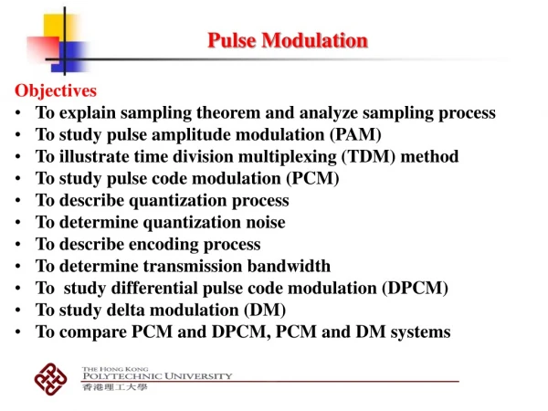
5.6 Pulse-Code ModulationPulse-Code Modulation • Pulse-code modulation (PCM) • Most basic form of digital pulse modulation • A message signal is converted to discrete form in both time and amplitude, and represented by a sequence of coded pulses • The basic operation • Transmitter: sampling, quantization, encoding • Receiver: regeneration, decoding, reconstruction
5.6 Pulse-Code ModulationOperations in the Transmitter • Sampling • The incoming baseband signal is sampled with a train of rectangular pulses at greater than Nyquist rate • Anti-alias (low-pass) filter • Nonuniform quantization • In real sources such as voice, samples of small amplitude appear frequently whereas large amplitude is rare. • Nonuniformquantizer is equivalent to compressor followed by uniform quantizer.
5.6 Pulse-Code ModulationOperations in the Transmitter • –law compressor • -law compressor
–law compressor Output level Quantization Input level
5.6 Pulse-Code ModulationOperations in the Transmitter • Encoding • To translate the discrete set of sample values to a more appropriate form of signal • A binary code • The maximum advantage over the effects of noise because a binary symbol withstands a relatively high level of noise. • The binary code is easy to generate and regenerate
5.6 Pulse-Code ModulationRegeneration along the Transmission Path • The ability to control the effects of distortion and noise produced by transmitting a PCM signal over a channel • Ideally, except for delay, the regenerated signal is exactly the same as the information-bearing signal • Equalizer: Compensate for the effects of amplitude and phase distortions produced by the transmission • Timing circuitry: Renewed sampling of the equalized pulses • Decision-making device
5.6 Pulse-Code ModulationOperations in the Receiver • Decoding • Regenerating a pulse whose amplitude is the linear sum of all the pulses in the codeword • Expander • A subsystem in the receiver with a characteristic complementary to the compressor • The combination of a compressor and an expander is called a compander. • Reconstruction • Recover the message signal by passing the expander output through a low-pass reconstruction filter
5.7 Delta ModulationBasic Considerations • Delta modulation (DM) • An incoming message signal is oversampled (at a rate much higher than Nyquist rate). • The correlation between adjacent samples is introduced. • It permits the use of a simple quantization. • Quantization into two levels () where is an error signal
5.7 Delta ModulationSystem Details • Comparator • Computes the difference between its two inputs • Quantizer • Consists of a hard limiter with an input-output characteristic that is a scaled version of the signum function • Accumulator • Operates on the quantizer output so as to produce an approximation to the message signal
5.7 Delta ModulationQuantization Errors • Slope-overload distortion • Occurs when the step size is too small • The approximation signal falls behind the message signal • Granular noise • Occurs when the step size is too large • The staircase approximation hunts around a flat segment.
5.7 Delta ModulationDelta-Sigma Modulation • Drawback of DM • An accumulative error in the demodulated signal • Delta-sigma modulation (D-M) • Integrates the message signal prior to delta modulation • Benefit of the integration • The low-frequency content of the input signal is pre-emphasized • Correlation between adjacent samples of the delta modulator input is increased • Design of the receiver is simplified
5.8 Differential Pulse-Code ModulationPrediction • Samples at a rate higher than Nyquist rate contain redundant information. • By removing this redundancy before encoding, we can obtain more efficient encoded signal. • If we know the past behavior, it is possible to make some inference about its future values. • Predictor • : prediction of • : prediction error • Implemented by tapped-delay-line filter (discrete-time filter) • : prediction order
5.8 Differential Pulse-Code ModulationDifferential Pulse-Code Modulation
5.8 Differential Pulse-Code ModulationDifferential Pulse-Code Modulation • Differential pulse-code modulation (DPCM) • Oversampling + differential quantization + encoding • The input of differential quantization is the prediction error. where is quantization error. • (5.38) is regardless of the properties of the prediction filter. • If the prediction is good, the average power of will be smaller than Smaller quantization error
5.9 Line CodesLine Codes • A line code is needed for electrical representation of a binary sequence. • Several line codes • On-off signaling • Nonreturn-to-zero (NRZ) • Return-to-zero • Bipolar return-to-zero (BRZ) • Split-phase (Manchester code) • Differential encoding
5.9 Line CodesLine Codes Bipolar return to zero(BRZ) On-off signaling Split-phase (Manchester code) Non return-to-zero(NRZ) Return-to-zero Differential encoding
5.9 Line CodesDifferential Encoding 0: Transition 1: No transition Reference bit: 1 Differential encoding