Download
1 / 40
530 likes | 2k Views
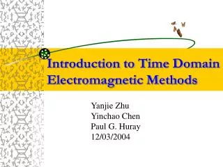
Introduction to Time Domain Electromagnetic Methods. Yanjie Zhu Yinchao Chen Paul G. Huray 12/03/2004. Outline. Comparison of different numerical methods Introduction to Finite Difference Time Domain (FDTD) Method Applications of FDTD to electrical engineering

E N D
Introduction to Time Domain Electromagnetic Methods Yanjie Zhu Yinchao Chen Paul G. Huray 12/03/2004
Outline • Comparison of different numerical methods • Introduction to Finite Difference Time Domain (FDTD) Method • Applications of FDTD to electrical engineering • Initial study of CFDTD to the detection of PCB impurities and surface roughness
Frequency Domain Methods MoM (Method of Moment) Zeland IE3DTM Agilent ADSTM (Advanced Design System) Ansoft EnsembleTM FEM (Finite Element Method) Ansoft HFSSTM UGS FEMAPTM Time Domain Methods FDTD Remcom XFDTDTM Zeland FidelityTM RM Associate CFDTDTM MRTD (Multi-Resolution Time Domain) PSTD (Pseudo-Spectral Time Domain) Comparison of different numerical methods
Principle of Finite Difference Derivative of f(x) at point P using finite difference approximations
Mesh Structure for FDTD Algorithm A standard Yee’s lattice
Implementation of FDTD Algorithm Starting point is Maxwell’s differential equations.
Selection of the parameters ★ Cell size criterion ★ Excitation choices Gaussian pulse: Blackman-Harris pulse:
Boundary Conditions Shielded boundary: Perfect Electric Conductor (PEC) Perfect Magnetic Conductor (PMC) Open boundary: Absorbing Boundary Condition (ABC) Perfectly Matched Layer (PML)
Calculation of MMICs Parameters The characteristic impedance Z0 is calculated by For a transmission line, the effective dielectric constant εeff is defined as: with: For a two-port network, S11 and S21 can be defined as: Input Impedance:
Using integral equation Conformal FDTD When the object to be simulated has curved surfaces and edges, the stair casing approximation of conventional FDTD technique can produce significant errors. Stair case: Conformal:
Applications of FDTD in Electrical Engineering • Simulation of Wave Propagation Problems • Microwave Engineering Problems • Antenna Problems • Scattering Problems • Signal Integrity Problems
Simulation of Wave Propagation I will show a simple 1dfdtd matlab code to clarify the wave propagation problem.
Conical Horn Antenna d1=0.71, d2=1.86, lt=1.08, l=3.75, =28degree
CFDTD ------------ Result
z y x Scattering Problems
Debye sphere 22.5 degree incidence dispersive, theoretical dispersive, FDTD Result
T1 T2 Port1 Port2 T3 T4 Signal Integrity Problem Structure Stack-up: Top View: 100mil*100mil Cell size: 0.7mil*0.7mil*0.35mil Frequency range: 10GHz-60GHz
Result Sig GND Sig GND Sig GND
Result Sig GND Sig GND Sig GND
Result Sig GND Sig GND
Comparison of field distribution on yz plane Without impurity With air bubble
Comparison of field distribution on yz plane With dielectric bubble εr=10 With PEC bubble