Download
1 / 40
400 likes | 416 Views
Detectors for the FCU. WSO/UV World Space Observatory / Ultraviolet Project. Michela Uslenghi INAF/IASF Milano. WSO/UV Italian web site: http://www.oact.inaf.it/wso/index.htm/. Outline. Overview of the Field Camera Unit UVO Detector CCD FEE NUV & FUV Detectors Requirements

E N D
Detectors for the FCU WSO/UVWorld Space Observatory / UltravioletProject Michela Uslenghi INAF/IASF Milano WSO/UV Italian web site:http://www.oact.inaf.it/wso/index.htm/
Outline • Overview of the Field Camera Unit • UVO Detector • CCD • FEE • NUV & FUV Detectors • Requirements • Selection process • Baseline architecture • MCP intensifier • Readout system • FEE • R&D WSO Detector Workshop
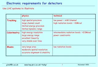
Imager requirements • Large wavelength coverage (115-700 nm) • Large field of view • High spatial resolution • Morphological studies (e.g. planets, planetary nebulae, star formation regions, external galaxies) • High accuracy stellar photometry • High accuracy stellar astrometry • Resolve stars in crowded fields (e.g. in star clusters, external galaxies, star formation in AGNs) • High time resolution in the UV WSO Detector Workshop
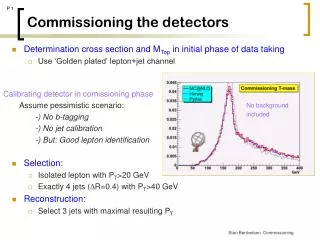
Science requirements for the FCU camera WSO Detector Workshop
UVO Channel NUV Channel FUV Channel FCU Layout WSO Detector Workshop
Enclosure UVO Channel UVO Filter Wheel Baffles Fore Optics Enclosure FUV Filter Wheel NUV Filter Wheel Detector NUV Channel FUV Channel S/C Optical Bench FCU Optical Bench Detector Baffle Detector Enclosure Mechanical Design WSO Detector Workshop
Operational Modes • Imaging (FUV, NUV, UVO) • Slitless spectroscopy (FUV, NUV, UVO) • Polarimetry (NUV, UVO) • Slitless spectro-polarimetry (NUV) • High Temporal Resolution Modes • Time Tag (MCP) • Windowing (CCD, MCP) WSO Detector Workshop
UVO Detector • The UVO channel will extend from UV to visual wavelengths • The pixel scale of this channel is a compromise between the need of a large field of view and high spatial resolution. • Filters, dispersers and polarizers narrow and broad band imaging, low resolution (R ~ 100-500) slitless spectroscopy and imaging polarimetry. • Single CCD detector optimized for the UV wavelength range. WSO Detector Workshop
UVO CCD • CCD device back illuminated with AR coating optimized in the UV range. • 4k 4k pixels • Pixel size will 15 m square • Exposures will be split in sub exposures with integration times ≤ 15-20 minutes (due to cosmic ray contamination) requirement on the dark current rate of 20 e–/pix/hr. WSO Detector Workshop
E2V CCD231-84 UVO channel CCD detector preliminary functional requirements WSO Detector Workshop
UVO detector package assembly(preliminary design) • Main components will be: • a baseplate. • a mounting support for the CCD • the CCD detector • a cover • a flat quartz window and optical baffles. • The baseplate will have holes for connectors and will host getter pumps to provide long term pumping against residual outgassing products. • There will be no FEE inside the package assembly. The FEE will be accommodated on the backside of the baseplate. Hermetic feedthroughs connectors will ensure electrical continuity between the CCD and the FEE PCB/ASIC. WSO Detector Workshop
CCD Readout • Operative modes: • Windowing: selection of a set of fixed sub-array apertures and user-defined sub-arrays • Binning: 2x2, 3x3, 4x4 • Gain: to fully exploit the CCD well capacity the controller must allow the selection of different gains WSO Detector Workshop
UVO CCD electronics system • Timing Board: Commands CCD exposures. Generates TTL level clocks for the CCD timing pattern. Generates biases digital data. • Clock Driver: translate the TTL level clocks to CCD clock voltages and send them to the CCD. • Bias Generator / Analog Signal Processing: translate the biases digital data generating the bias voltages to operate the CCD. Digitize the signal from the CCD outputs to 16-bit accuracy. • Low Noise Preamps: receive the signal from each of the CCD outputs and send it to the analog signal processing board. WSO Detector Workshop
Requirements for NUV&FUV detectors WSO Detector Workshop
Some considerations on detector choice • Directions from the science team: the more important characteristic is the spatial resolution (in particular for the NUV) • Very short WSO schedule: no R&D • Looking for something available now. Delivery time should fit the schedule • Avoid (if possible) ITAR WSO Detector Workshop
Baseline configuration of the UV detectors • PC-ICCD • Photocathode • 2-3 stages MCP intensifier • Phosphor screen • Fiber Optic taper • High speed CCD camera • Real time digital electronics unit WSO Detector Workshop
FUV & NUV Detectors FUV & NUV Channel: MCP-based detector in sealed configuration Format: 2kx2k (40mm) Read-out system: CCD Photocathodes: CsI (FUV), Cs2Te (NUV) WSO Detector Workshop
Photek 40 mm WSO Detector Workshop
MCP intensifier • MCP 2-stages (Chevron) • Diameter 40 mm • Pore size 10 m (12 m) • L/D I 50:1 II 80:1 • Gain 5•105 e- • Pulse Height Distribution (PHD) <125% FWHM • PHD spatial variation <10% peak-to-peak • Dark Counts @ 20C <1 counts/cm2s • Photocathode CsTe/CsI • Window MgF2 • Phosphor screen P46 • Sealed configuration WSO Detector Workshop
Photocathodes WSO Detector Workshop
CsI Photocathode DQE for the CsI coated ACS SBC MCP Photek data Semitrasparent vs opaque photocathode WSO Detector Workshop
CCD Readout sensor Sarnoff VCCD-512 • Format 512 x 512 pixels • Pixel size 18 x 18 m2 • Architecture Splitted FT • Full well 240,000 e- • Fill factor 100% • N. of output Ampl. 16 • Readout frequency 10 MHz (per amplifier) • Frame rate 500 frames/s • Require: • 4x centroid subpixel resolution WSO Detector Workshop
PC-ICCD Electronics Overview • The detector electronics include two main blocks: • an Analog Front-End Electronics (AFEE), an high speed front-end CCD electronics • a Digital Front-End Electronics (DFEE) with a real time data processing unit, which will acquire the data from the CCD camera, search for the photon events and computes the coordinates of the detected photons with sub-pixel accuracy • Filters for the High Voltage Power Supply should also be located close to the detectors. ICU WSO Detector Workshop
DFEE: data processing and centroiding The DFEE will acquire serially the CCD digitized output signals + sync signals (frame, line and pixel sync), reorder them (if required), and subdivide the frame in sub-regions to be analyzed by parallel processors, each one implementing the following tasks: • through a proper system of delays, the processor will generate 33 pixel windows that sweep dynamically the whole matrix to be analyzed at the pace of the pixel clock; • on each window: • check, according to appropriate discrimination and pile-up rejection criteria, for the presence of a charge distribution representing a photon event; • compute the centroid coordinates with a centre of gravity algorithm to the charge distribution in the current window and correcting for systematic errors. All the operations should be done in real time no limits should be introduced by the electronics on the dynamic range implementation in FPGA, adopting a pipeline architecture in order to process the data at the rate they are generated by the sensor WSO Detector Workshop
System Overview WSO Detector Workshop
Local Dynamic Range WSO Detector Workshop
LDR translated to magnitudes … Low limit: High limit: V Johnson Range: 8.9 magnitudes WSO Detector Workshop
UV detectors data flux SDMU The DFEE produces a 32-bit word for each detected photon, with the x,y,t coordinates (plus “amplitude”, used for monitoring). These words are sent, via Spacewire interface to the ICU. Operative mode (science + calibration) are (software) implemented in the ICU At least two operative modes (+windowing) will be implemented for science observations: • time tag mode: photon list {x,y,t} is sent to the SDCU and then to ground. Data rate depends on the flux of incoming photons (which in turn depends on filters and sources in the field) • accumulation mode: before sending them to the SDCU, counts are accumulated by the ICU in an array in which each element correspond to a pixel, eventually producing a CCD-like image limit data rate by loosing time information, allowing exposures with high count rate. WSO Detector Workshop
Model Philosophy (Moscow) Our proposal: • Bread Boards (not deliverable) • Structural Thermal Model (deliverable, should be returned) • Optical Bench • Mass dummies • Thermal dummies • Engineering Model (deliverable) • Mock-up optics and detectors • Functional representative of the flight model at Bus functional I/F level • Optical Bench: Initially could be a plate to be replaced by OB when performing EMC tests or bus mechanical/functional integration tests. • Flight Model (deliverable) • WSO-UV plans • Full Scale Model – MSM (May 2008) • Mass Model + Structural Model • Thermal Equivalent – TM (Jan 2009) • Technological Model – EM (Jan 2009) • Instrumentation Flight Set Model – FM (May 2009) WSO Detector Workshop
PC-ICCD for ground-based astronomy WSO Detector Workshop
Array Size 2048 2048 pixel (1) 2048 512 pixel (2) Pixel Size 13.5 13.5 m2 Spatial Resolution 25 m (FWHM) @ 550 nm 30 m (FWHM) @ 254 nm Time Resolution 16.8 ms (1) 4.512 ms (2) Detective Quantum Efficiency (DQE) 8.2% @ 229 nm 6.8% @ 254 nm Visible Light DQE 0.074% @ 405 nm Spectral Range (DQE 1%) 120-300 nm Dark Count Rate 1.74 cts s-1cm-2 Local Dynamic Range (DQE loss < 10 %) 13 cts s-1 (1) 54 cts s-1 (2) Global Dynamic Range (DQE loss < 10 %) 2.6 104 cts cm-2 s-1 (1) 9.2 104 cts cm-2 s-1 (2) PC-ICCD characteristics WSO Detector Workshop
Spatial Resolution Readout system: FWHMx~ 5 m Front MCP pore structure fully resolved Detector: FWHMx~ 25 m @ 5500Å limited by proximity focus WSO Detector Workshop
Dynamic Range • 10% fractional count rate loss: • Local: • 13 cts/s @ full frame • 54 cts/s @ window • Global: • 2.6·104cts cm-2 s-1 • 9.2·104cts cm-2 s-1 WSO Detector Workshop
Asiago-Cima Ekar • 182 cm Telescope + AFOSC (3 filter wheels allowing combination of: photometric filters, grisms, Echelle grisms, polarimeter based on a double Wollaston prism) • High speed Photometry & spectroscopy of CV & Flare stars WSO Detector Workshop
Crab Pulsar • PFFT=0.0334881±1.5·10-7 s • PEF=0.033488256±8·10-9 s WSO Detector Workshop
1WGA 1958.2+3232 WSO Detector Workshop
Objective Holder Light Tight HV Connector CMOS - APS MCP Electronic Board Lens Objective PC-IAPS 1024x1024 pixel 1024 8-bit ADC on chip (one for each column) 8 parallel outputs Up to 500 frame/s full frame (+windowing) WSO Detector Workshop
PC-IAPS FEE Board The APS is mounted on a 10 cm x 10 cm PCB board, which also hosts the driving electronics, the real time data processing unit and the interfaces to the host PC. The core of the electronics is a single FPGA, XILINX XCV 800 (800 Kgates equivalent), allowing a very compact design. WSO Detector Workshop
PC-IAPS FEE Overview • At each clock pulse, the 64 bits data output (8 pixels x 8-bit) are acquired by the data processor. • Synchronous FIFO are used as delay line that allows a concurrent sampling of a pixel together with its nearest neighbors. • Upon initialization, a set of D-Latches is used to map 8 windows of 3x3 pixels, which covers dynamically the whole APS image at the pace of the pixel clock. This allows the whole APS frame to be analyzed, avoiding problems of either fixed or dynamic image partitioning. • The processing system performs in parallel the following tasks on each window: Check (discrimination and pile-up rejection criteria) for the presence of a photon event; compute the centroid coordinates and transfer them to a PC. WSO Detector Workshop