Download
1 / 24
240 likes | 274 Views
Learn about the Pulsed Modulation PHY technology enabling data rates from 1 Mbit/s to 100 Mbit/s, with focus on spectral efficiency, reach, and adaptability to varying channel conditions. Explore the use of 2-PAM, 8B10B line coding, M-PAM with HCM, and RS FEC for rate adaptation and reliability in MIMO scenarios.

E N D
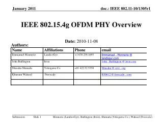
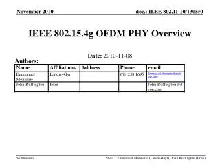
IEEE 802.15.13Introduction into Pulsed Modulation PHY Date: 2018-04-25 Place: Warsaw, Poland Authors: Volker Jungnickel (Fraunhofer HHI)
Abstract This presentation provides an overview of the pulsed modulation PHY in doc. 15-18-0003/r2 discussed in TG13. Volker Jungnickel (Fraunhofer HHI)
Table of Content • Physicallayers in TG13 • Pulsedmodulation PHY • Numerology • PPDU format • Fields • Synchronization • Channel estimation • Header • MIMO referencesignals • Payload Volker Jungnickel (Fraunhofer HHI)
Physical Layers in TG13 High-bandwidth OFDM PHY Spectral Efficiency LB OFDM PHY Pulsed Modulation PHY Bandwidth Shannon’s theorem: C=B*log2(1+SNR) C: Channel capacity, B: Bandwidth, SNR: electrical Signal-to-noise ratio Slide 4 Volker Jungnickel (Fraunhofer HHI)
Pulsed modulation PHY • Why? • 100 Mbit/s = 10 MHz * 10 bps/Hz needs a very high SNR ~ 30-40 dB • 100 Mbit/s = 100 MHz * 1 bps/Hz needs 3dB x 9 =27 dBless electrical SNR • Higher bandwidth 20x less optical power (Uplink, Internet of Things) • Pulsed Modulation PHY (PM PHY) • Target is 10…100 Mbit/s with low power for enhanced coverage • High bandwidth useful with special LED drivers • Lower SNR lower spectral efficiency • Serial modulation with Reed-Solomon Coding, 2-PAM and 8B10B line coding or M-PAM with Hadamard-Coded Modulation (HCM) • Rate adaptation through variable M and variable number of HCM codes • Support for MIMO spatial diversity, reliability Slide 5 Volker Jungnickel (Fraunhofer HHI)
Descriptive Text • Pulsed Modulation PHY Pulsed Modulation PHY enables moderate data rates from 1 Mbit/s to some 100 Mbit/s. The main approach is to achieve high data rates by using high bandwidth while keeping spectral efficiency low. This approach offers higher reach where power efficiency is an issue, e.g. in uplink scenarios and the Internet of Things (IoT). 2-PAM with 8B10B linecodingand variable opticalclock rate or M-ary PAM withHadamard-Coded Modulation (HCM) areusedtogetherwith RS FEC. Controlled by higher layers, the PM PHY includes means to adapt the data rate to varying channel conditionsi) by varying the optical clock rates, ii) by varying the modulation alphabet size M for PAM and the number of codes used in HCM and iii) by selecting the most appropriate set of transmitters. Volker Jungnickel (Fraunhofer HHI)
Numerology Optical clock rates (OCR) in Table 1 are obtained from a common reference clock of 100 MHz available from low-cost off-the-shelf crystal oscillators as 100 MHz/2n where n=-1…4. The reference clock can also be obtained via Ethernet using the precision time protocol (PTP) defined in IEEE std. 1588v2. Jitter can be improved by adding synchronous Ethernet (synchE) defined in ITU-T recommendation G.8262. Volker Jungnickel (Fraunhofer HHI)
Optional Fields PHY header HCS Preamble Channel estimation PSDU PPDU format PHY payload SHR PHR • Synchronization header • Channel estimation • Physical layer header with header check sequence • Optionial fields for MIMO channel estimation • PSDU for payload Volker Jungnickel (Fraunhofer HHI)
Synchronization preamble • ANis pseudo-noise : Gold sequenceoflength N a) Preamblelength L = 2xN (N=31, proposedby ETRI) • double-wordandautocorrelationisstandardapproach b) Preamblelength L = 6xN (N=16, 32, 64, proposedby HHI) • 6-fold repetition shorterpeak improveddetection • Pulsedmodulationrequireszerotimingerror P2xN = [AN AN] P6xN = [AN AN -AN AN -AN -AN] Volker Jungnickel (Fraunhofer HHI)
Channel estimation • Channel estimation (CE) is used for equalization and subsequent detection of header information and data. • The CE sequence allows frequency-domain equalization by adding a cyclic prefix (CP). There is a base sequence AN with N=Nseq in Table 1and a cyclic prefix CP. • By increasing the OCR, the number of optical clock cycles for the sequence and CP, i.e. Nseq and NCP, increase proportionally, see Table 1. • The CE sequence is finally passed through a 2-PAM modulator. Volker Jungnickel (Fraunhofer HHI)
PHY header • The PHY header has a fixed length and defines the following fields. Volker Jungnickel (Fraunhofer HHI)
PHY header fields • FT defines the frame type • FT=0: Transport frame (used in MAC e.g. for Data, RTS, CTS, ACK, Feedback, Control) • FT=1: Probe frame (used for MIMO channel estimation) • FT>1 Reserved • The PSDU length scales from 0 up to aMaxPHYFrameSize. • RS_type defines the use of time- or frequency-domain RS. • NRS is the number of RS. • Time stamp is a number counting time (e.g. in 10 ns units per second). Time per second is obtained from the one-pulse-per-second (1 PPS) signal from GPS or PTP grandmaster. Additional time information can be obtained via higher layers. • MCS defines the modulation and coding scheme (see next slide). Volker Jungnickel (Fraunhofer HHI)
MCS field • MCS defines the used modulation and coding schemes defined by the MAC layer. • For single-stream transmission, MCS is a number. • For spatial multiplexing transmission, MCS is a vector where each element contains the MCS per stream. Volker Jungnickel (Fraunhofer HHI)
Header check sequence The header check sequence (HCS) uses CRC-16 as defined in Annex C. The HCS bits shall be processed in the transmitted order. The registers shall be initialized to all ones. Note that „Annex C“ refers to the Annex in TG13 Draft D2. Volker Jungnickel (Fraunhofer HHI)
Optional fields Optional fields contain reference symbols (RS) for multiple-input multiple-output (MIMO) channel estimation. Repetitions, FEC, line coding and HCS do not apply for MIMO RS. MIMO RS can be defined in time- and frequency domain. The use of time- or frequency-domain RS is configured by the MAC layer. • At lower OCR, time-domain MIMO RS are appropriate. • At higher OCR, frequency-domain MIMO RS apply. Volker Jungnickel (Fraunhofer HHI)
Time-domain MIMO RS • Time-domain (TD) MIMO RSs are constructed as follows: • for the ith data stream/transmitter use the ith row of the NxNHadamard matrix HK where N=Nseq. HK is given by • increment k from k=1…K with N=2K. The resulting sequence is scrambled by logical XOR operation with the base sequence AN. A cyclic prefix is finally inserted. • All pairs of sequences in HK are mutually orthogonal. The XOR operation with AN does not change the orthogonality of sequences but improves cross-correlation properties which is beneficial in case of multi-path [5, 6]. • Note that the sequence for the first stream/transmitter always contains AN. Volker Jungnickel (Fraunhofer HHI)
Frequency-domain MIMO RS • Frequency-domain (FD) MIMO RSs apply for transmissions at higher OCR using FDE. • FD MIMO RS are orthogonal in the frequency domain. • FD MIMO RSs are a set of NRS OFDM symbols constructed by using the base sequence AN where N=Nseq according to Table 1 as follows. • A specific comb of subcarriers identifies a particular stream or transmitter. • Comb spacing Δ is defined by higher layers taking Δ≤Nseq/NCP into account. • The definition of Δ is contained in ERS_type and IRS_type. • There are Ncomb=Nseq/ Δ non-zerosignals (tines) in the comb. The base sequence AN where N=Ncomb yield an appropriate definition of the signals on these tines. • For the first stream/transmitter, the comb starts at the first subcarrier following the DC subcarrier onto which the first element of AN is mapped, while other subcarrier carry the other elements of AN consecutively. • By using a single FD MIMO RS, up to Δ-1 streams/transmitters can be identified by a cyclic shift of the comb by Nshift=0…Δ-2 of subcarriers. • The MAC layer shall reserve the shift Nshift = Δ-1 for noise estimation at the receiver. Volker Jungnickel (Fraunhofer HHI)
Frequency-domain MIMO RS (2) • Any subset of streams/transmitters smaller than Δ-1 can be identified by a single FD MIMO RS. When using more streams or transmitters, add more RSs. • Higher layers shall indicate the use of MIMO RS by variables Δ and NRS, where index RS means ERS and IRS, accordingly. • In order to keep RSs for multiple subsets of streams/transmitters mutual orthogonal, the mth RS is obtained by multiplication of the appropriate RS with the respective elements from the mth row of the MxMHadamard matrix HK identifying the mth subset of RSs using the same cyclic comb shift. • HK is obtained as follows • where k=1…K and M=2K=NRS is defined by higher layers. Volker Jungnickel (Fraunhofer HHI)
Header encoding and modulation Scrambling is optional to randomize uncoordinated interference. For error protection, the header can be repeated. Next, 8B10B line encoding applies to the header. Header encoding uses RS(36,24) code. • In this way, only the systematic part of the binary output code word (24 bits) is well balanced. For maintaining a constant average light output for the entire sequence, also the redundant part of the binary code word (36-24=12 bits) has to be passed through the 8B10B line encoder. Both parts are concatenated in a multiplexer. Next the signal is passed through the bit-to-symbol mapper for 2-PAM modulation. • The bit-to-symbol mapper is using 2-PAM. Each input bit is mapped in one symbol. Symbols are mapped to levels as {0, 1} to {0, 1}, respectively. A constant value of 0.5 is always subtracted to make the mapper output DC free. Setting the modulation amplitude and the bias signal of the LED is due to the analogue optical frontend. Finally, a spatial pre-coder selects what transmitters will sent out the packet and how. Volker Jungnickel (Fraunhofer HHI)
Payload encoding and modulation • Scrambling is optional to randomize uncoordinated interference. • Next, 8B10B line encoding applies to the payload. • Payload encoding uses RS(256,248) code. In this way, only the systematic part of the binary output code word (248 bits) is well balanced. For maintaining a constant average light output for the entire sequence, also the redundant part of the binary code word (256-248=8 bits) has to be passed through the 8B10B line encoder. Both parts are concatenated in a multiplexer and passed through the bit-to-symbol mapper for 2-PAM modulation. • In combination with Hadamard Coded Modulation (HCM) other than the trivial mode HCM(1,1), 8B10B line coding is not used while M-PAM with M≥2 can be used. • Finally, a spatial pre-coder selects what transmitters will sent out the packet and how. Volker Jungnickel (Fraunhofer HHI)
Bit-to-symbol mapper Volker Jungnickel (Fraunhofer HHI)
Hadamard-coded modulation (HCM) Hadamard Coded Modulation (HCM) is an extension of the bit-to-symbol mapper. Besides removing the need for line coding, HCM allows the use of M-PAM with variable M, despite the high-pass characteristics of the channel, together with a variable number of codes. Volker Jungnickel (Fraunhofer HHI)
Transmission modes for PM-PHY • The table lists possible transmission modes by combining line coding, FEC, HCM and OCR. In combination with Table 1, it is possible to obtain the data rate for each transmission mode. • Using RS(256,248) with 2-PAM, 8B10B and n=4 (6.25 MHz) yields 4.8 Mbit/s. • Using RS(256,248) with 16-PAM, m=15 for HCM and n=0 (100 MHz) yields 363 Mbit/s. Volker Jungnickel (Fraunhofer HHI)
Spatial precoder • In general, the spatial precoder is a matrix-vector operation P·xoperating symbol-wise when using time-domain RS and subcarrier-wise when using frequency-domain RS. • If FT=0 (probe frame), the transmitter multiplies the 1x1 scalar stream of header symbols x with the NERSx1 vector Pwhich contains all ones. • All transmitters broadcast the same header information (global transmission). The master coordinator in the infrastructure network sends the header information to all transmitters. All transmitters send in a synchronous manner. How to realize synchronization of multiple distributed OWC transmitters is out of scope for this standard. • If FT=1 (transport frame), the transmitter multiplies the 1x1 stream of header information symbols xwith the NERSx1 precoding vectorP which contains ones for all active transmitters in a coordinated transmission cluster and zeros elsewhere. • All transmitters in the cluster broadcast the same header information (regional transmission). The master coordinator in the infrastructure network sends header information to all active transmitters in a coordinated transmission cluster. All transmitters send in a synchronous manner. How to realize synchronization of multiple distributed OWC transmitters is out of scope for this standard. Volker Jungnickel (Fraunhofer HHI)