Download
1 / 37
370 likes | 519 Views
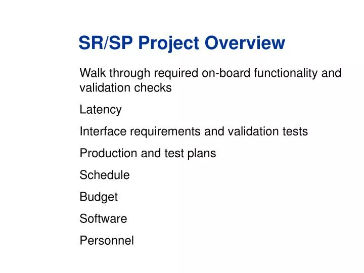
Walk through required on-board functionality and validation checks Latency Interface requirements and validation tests Production and test plans Schedule Budget Software Personnel . SR/SP Project Overview. Documentation. . . Principles of CSC Track-Finding.

E N D
Walk through required on-board functionality and validation checks Latency Interface requirements and validation tests Production and test plans Schedule Budget Software Personnel SR/SP Project Overview
Documentation SR/SP Project Overview, US-CMS Electronics Review
Principles of CSC Track-Finding • Link local track segments into distinct 3D tracks (FPGA logic) • Reconstruction in suppresses accelerator muons • Measure pT, , and of the muon candidates in the non-uniform fringe field in the endcap iron (SRAM LUTs) • Require 25% pT resolution for sufficient rate reduction • Send highest qualitycandidates to Sorter and then to GMT • Partitioned into 60° sectors that align with DT chambers SR/SP Project Overview, US-CMS Electronics Review
PT Measurement Can use information from up to 3 chambers (Exploring use of local bend angle when only 2 stations available) Df Pt LUT 4 MB 2 PT 1 Pt = f(Df12, Df23 , h ) IP Residual Plot Constant Pt Contours for: 3, 5 ,and 10 GeV ms. Res=22% SR/SP Project Overview, US-CMS Electronics Review
CSC Track-Finder Crate Single crate solution, 2nd generation prototypes Clock & Control Board Sector ReceiverSector Processor SR SR SR SR SR SR SR SR SR SR SR SR CCB MS / / / / / / / / / / / / SP SP SP SP SP SP SP SP SP SP SP SP From MPC SBS 620 Controller (chamber 4) Muon Sorter From MPC (chamber 3) From MPC (chamber 2) From MPC (chamber 1B) From MPC (chamber 1A) To DAQ • 180 1.6 Gbit/s optical links: • Data clocked in parallel at 80 MHz in 2 frames (effective 40 MHz) • Custom 6U GTLP backplane for interconnections (mostly 80 MHz) • Rear transition cards with 40 MHz LVDS SCSI cables to/from DT SR/SP Project Overview, US-CMS Electronics Review
SP2002 Main Board (SR Logic) Follow functionality of board from input to output Phi Global LUT PLL patch Eta Global LUT Phi Local LUT Front FPGA To/from custom GTLP back-plane TLK2501 Transceiver • Optical Transceivers • 15 x 1.6 Gbit/s Links SR Logic SR/SP Project Overview, US-CMS Electronics Review
Optical Link Tests • Data format from MPC and synchronization procedure specified in document (linked off web page) • In-crate optical loop-back PRBS tests using external clock source and no PLL demonstrates about 1 error / hour (BER~10-12) • Demonstrated to maintain synchronization with LHC-like structured beam during Sept’03 beam test with home-built PLL+VCXO and with latest QPLL (TTCRq) • Two modes of data transmission with MPC: “framed” or “continuous” • No link errors observed with either mode • Overall agreement with EMU data logged via DDU @ 99.8% level • Remaining issues with DDU data integrity, software • Repeated during 2004 beam test SR/SP Project Overview, US-CMS Electronics Review
SR Memory Scheme Phi Global LUT Phi Local LUT DT -12 to Barrel FRONT FPGA SP FPGA GS840F18 256K x 18 GS8160132T 512K x 32 S CLCT Patt. - 4 local - 10 RD 0:15 REG FIFO Quality - 3 local -10 appr. - 5 Flowthrough SRAM 1/2 Strip - 8 CSC -12 b local - 6 CSC_ID - 4 Flowthrough SRAM L/R Bend 1 CSC_ID – 4 appr. – 7 RG 2 Eta Global LUT RX_CLK WCL RCL GS88018A 512K x 18 b local - 6 b,CSC - 5 local - 2 CSC_ID - 4 CSC- 6 appr. - 7 Flowthrough SRAM 40 MHz 40 MHz(180) 40 MHz( 0) DLL 80 MHz 40 MHz Provides data conversion into tracking variables and applies alignment corrections SR/SP Project Overview, US-CMS Electronics Review
LUT Features and Tests • 2 BX latency • 45 SR LUTs (only 11 distinct per SR/SP), >40MB • 3 PT LUTs (all identical) • Can multicast when loading chips, boards • Validated loading and read-back of all 45 SR LUTs and 3 PT LUTs using random numbers and simulated muon LUT files • Used during 2004 beam test, no errors observed in logged SP output when compared to simulation using logged SP inputs • ORCA trigger simulation implements LUT scheme, so all resolutions obtained using it • Quite flexible • Changes made to work with beam test geometry SR/SP Project Overview, US-CMS Electronics Review
SP2002 Track-Finder Logic • Xilinx Virtex-2 XC2V4000~800 user I/O • Same mezzanine card is used for Muon Sorter • Track-Finding logic operates at 40 MHz • Frequency of track stub data from optical links • About 50% of chip resources (LUTs) used • Easily upgradeable path • 12 months engineering for new transition card SP2002 mezzanine card SR/SP Project Overview, US-CMS Electronics Review
SP Firmware • FPGA firmware is synthesized from Verilog • Top-level schematic connects Verilog blocks • Core track-finding logic is actually written in C++ and converted to Verilog using a special C++ class library written by our engineer, A.Madorsky • Two compiler options for one piece code: • Compiled one way, the C++ program self-generates Verilog output files which are human-readable and from which can be synthesized by the FPGA vendor tools • Compiled another way, the same code exactly emulates the behavior the digital logic • Solves main obstacle to validation of the first TF prototypes • Allows use of free compiler tools on commodity PC’s for debugging • Still need vendor simulation tools for other FPGAs • This SP logic is implemented in the ORCA simulation and reconstruction framework and is now the default (7.7.0) SR/SP Project Overview, US-CMS Electronics Review
Recent Updates to Track-Finder Logic • Firmware improvements • Multiple-BX input acceptance for track segments • Improves efficiency, used at 2004 beam test • Track-Finding parameters under VME control (e.g. windows) • Error counters, track segment counters, track counters for monitoring and alarms • Ghost-busting at sector boundaries • Increases di-muon trigger acceptance to ||<2.4 when low quality CSC tracks included • Installed into ORCA • Self-trigger capability (for beam tests and slice tests) • A Level-1 Request signal can be generated based on the presence of a track for beam test use • Goes onto bussed backplane to a specially modified CCB2001, then out front-panel SR/SP Project Overview, US-CMS Electronics Review
Track-Finding Test Validation • Downloaded random data and simulated muon data into 512 BX input FIFO, read-back and compare output FIFO • No discrepancies in 1.2M random events • No discrepancies in 13K single muon events, or 4K triple muon events (3 single muons piled up) • Complete functionality test passed • Utilizes bi-directional capability of SR/SP links • Input FIFO Optical loopback Front FPGA LUTs Track-Finding output FIFO (all 15 links) • Also checked behavior during 2004 beam test by comparing logged output against emulation based on logged inputs • Perfect agreement for 150K events SR/SP Project Overview, US-CMS Electronics Review
Remaining Track-Finder Firmware Tasks • Implementation of a “halo muon” trigger • To identify through-going muons parallel to beam axis simultaneously with collision muons (but at reduced rank) • Logic still needs writing, once simulation study performed to determine appropriate criteria (must reconvert back to WG) • Trivial to implement a stand-alone halo muon trigger by just changing LUT contents (as at beam test) • Improvements to PT assignment • Simulation studies continue to show ways to improve efficiency and rate reduction capability • New statistical approach to PT assignment • Usage of LCT pattern (bend angle) to identify low PT muons • TeV muon recovery logic (trajectory cleaning with 4 stations to remove bad hits from showers) • Added as developed (student projects) SR/SP Project Overview, US-CMS Electronics Review
CSC Track-Finding Logic & Latency 11 25 ns, or 275 ns Big improvement over 1st prototypes (21 bx) SR/SP Project Overview, US-CMS Electronics Review
CSC Trigger Latency • Measured with scope during 2003 beam tests: • From CSC to MPC input: 32 bx ( 1 bx) • From the CSC to SR/SP input: 57 bx(includes 90 m fiber, 18 bx delay) • Estimated latency for output of SP: • Add 11 bx for SR/SP processing: 68 bx • Estimated latency for output of Muon Sorter: • Add 7 bx for backplane + sorting: 75 bx • Total compares well with 73.5+1 bx projected in TDR • (+1 bx for TOF delay) • Expect to save additional ~7 bx with “Virtex-2” TMB • Estimated latency to send CSC data to DT TF: • 1bx TOF + 57bx + 5bx for SR + 2bx cable: 65 bx – 7 bx = 58 bx • Nearly aligned with DT data at DT TF: 54 bx according to TDR SR/SP Project Overview, US-CMS Electronics Review
Interface Tests • MPC to SR/SP • Validated with optical link tests on bench and at beam tests • Two MPCs (two crates) to SR/SP demonstrated @ beam test ‘04 • SR/SP to Muon Sorter Test • Data successfully sent from SP to Muon Sorter on bench and received properly. Read-back of winner bits also correct. • Tested 10/12 slots on custom GTLP backplane • Tested at beam test ’04, read back of winner bits OK • Full chain test from CSCs, • Two SP to MS also tested at beam test (not checked yet) • Clock and Control Board (TTC interface) • Both CCB2001 and CCB2004 (with TTCRq) tested and work with SR/SP • Issue with orbit signal under investigation • DT/CSC Data Exchange Test • Demonstrated to work during Sept’03 in both directions, with only a few minor problems with swapped bits, connectors, and dead chips • New transition card designed and tested in loop-back mode SR/SP Project Overview, US-CMS Electronics Review
First DT/CSC Integration Tests DT TF transition card CSC TF transition card SR/SP Project Overview, US-CMS Electronics Review
DT/CSC Transition Card Test • While we were waiting for beam to start at CERN, we managed to test a new DT/CSC transition card for the Track-Finder • New design solves connector space problem • Tester board allows loopback test without DT Track-Finder • Data pumped from input FIFO to output FIFO on SP • Data test succeeded, except for 1 broken backplane pin • Next step: • Second integration test with DT TF (Oct.’04 or later) • Janos Ero reports new PHTF is partly assembled and tests are beginning SR/SP Project Overview, US-CMS Electronics Review
DAQ Interface • Current SR/SP DAQ output used at beam tests is through VME readout • Final version will be read out through a DDU board via SLINK • One output optical link per SP 12 links / DDU (out of 15) • DDU slot included on TF backplane • Earlier agreement was that we would wait until new OSU DDU design is ready before working on SP-DDU tests, and not hold up SR/SP production • New DDU has been produced, but still to be tested in DAQ system at upcoming beam test • Estimate for firmware development + testing is 3 months once documentation from OSU is available • Software may be in good shape since DDU already supported by EMU in XDAQ environment SR/SP Project Overview, US-CMS Electronics Review
Full CSC Track-Finder DAQ Data Format • Full (i.e. final) DAQ output format of CSC SR/SP specified • CSC Track-Finder logs all input and output data for several BX around L1A (7 BX max) • Zero suppression capability (valid pattern) • Includes MS winner bits • Implemented in firmware, and tested at beam test • Data unpacking software written • All TF test studies based on it SR/SP Project Overview, US-CMS Electronics Review
DAQ Bandwidth • Average SR/SP event size @ beam test with 4 CSCs was 88 bytes with zero suppression and headers • Early LCT simulation studies (Cousins et al.) show an occupancy of about 0.9 LCT/BX @ high lumi • Neglecting neutron-induced LCTs • Suppose L1 trigger menu is 50% jets (CSC occup ~ 0.5) and 50% single muons ( 50% in endcap 4 LCTs), and assume pile-up is 0.9 3 BX readout 4 LCTs/L1A • TF crate DAQ Bandwidth = 88 bytes 100 kHz = 9 MB/s • Well within the 200 MB/s specification of the SLINK out of the one DDU in the TF crate • Bandwidth to tape @ 100 Hz 9 kB/s SR/SP Project Overview, US-CMS Electronics Review
Production and Test Plans • Will assemble 1 or 2 boards first as pre-production prototype and test before launching full production (12 SR/SP + 3 spare) • To begin October 2004 • Lev currently scheduled to arrive @ UF Sept. 23 • Each of the prototype tests (optical link PRBS tests, LUT tests, TF logic, etc.) will become standard tests for the production modules • We have a suite of tests in our XDAQ-based software with a JAVA interface • Initial testing will be performed by engineer (Lev) or students (Kotov, Gray/Park) • Encountered problems will be addressed by our engineers • Integration tests at CERN to be led by a postdoc to be hired SR/SP Project Overview, US-CMS Electronics Review
Schedule • SR/SP: • Schematics ready Sept.5 • Layout ready Sept. 26 • Production to launch Oct. ’04 • First pilot samples for testing available mid-November • Assume about 1 month for thorough testing • Rest of main board production to commence by Jan. ‘05 • Production complete Feb. ’05 • Production tests complete Apr. ’05 • TF backplane: • Above tests performed with existing prototype backplane, launch TF backplane production if OK • Complete by Mar. ’05 • DT/CSC transition card: • To proceed after second prototype tests with DT TF • Ready for tests with new boards at Bat. 904 Apr. ‘05 SR/SP Project Overview, US-CMS Electronics Review
Possible Negative Impacts on Schedule • October 25 ns beam test • Currently I do not plan to send an engineer (Lev), unless entry to U.S. is delayed and a meeting at CERN is useful for production discussions as well • DT/CSC test • Latest PHTF prototype is fabricated and partly assembled. I previously judged Vienna’s schedule to be ready for 25 ns beam test (and subsequently our interface test) to be too aggressive, but it appears J.Ero is still counting on a test in October. • If test is really feasible this year, plan could be to launch SR/SP main board production, and while waiting for boards to return try to conduct test at CERN (visa issues remain though) SR/SP Project Overview, US-CMS Electronics Review
Integration Tests • Tests to be done at Prevessin needs clarification • Full chain tests from CSC to MS have been performed on the bench in the U.S. and particularly at beam tests at CERN • With respect to SR/SP, remaining tests include • SP-DDU: can be done on bench in U.S. • DT-SP: second test with new DT TF and new DT/CSC card can be done on bench at UF or CERN or Prevessin • SP-DAQ: FMM path to Global Trigger, at Previssin? at UX5? • Slice Tests at SX5 will be useful to enable more than 2 MPCs in more than two PCs to connect to TF crate • But it is hard to imagine how we will ever test more than one sector (>1 SP) before installation in UX5 • Nevertheless, there is certainly a lot of software to be written for trigger configuration, monitoring, emulation, and analysis SR/SP Project Overview, US-CMS Electronics Review
SR/SP Budget Estimate • Detailed, conservative, cost estimate performed • FPGAs: $4.1K/board, $49K total, $66K in Project • Main FPGA: $1.1K/chip, 20 procured with TMB order • Others + EPROMs: $3.0K • Optics: $1.4K/board, $17K total, $45K in Project • Working on ordering remaining quantity of original part #(Pin compatible replacement also available, but not tested) • TLK included • Misc: $2.0K/board, $24K total, $55K in Project • Includes LUTs, mezzanine and transition cards • Setup, Fab., Ass.: $6K/board, $72K total, $70K in Project • Main board + mezzanine + transition cards • Estimated total: $14K/board • Sum of Project: $20K/board SR/SP Project Overview, US-CMS Electronics Review
Spares • Project has budget of $58K for spares in addition to production costs • We would like to assemble 4 spares + parts for 2 more given the small number of boards involved • Critical parts ordered or in hand already • Optical components • Need (12+4+2 boards)*(15+1 links) = 288 for SR/SP • Rice wants 220 for MPC, including spares • We will try to order about 500 total for both projects, currently ordered last 409 from one vendor • Main FPGA (on mezzanine card) • We have 17 in hand, with original agreement for 20 from Jay • This should be enough for SR/SP and MS • PT LUTs • Minimum quantity was 72, used 9 for SP2002, we need 54 more for 12+6 boards, so plenty of spares SR/SP Project Overview, US-CMS Electronics Review
TF Backplane Budget • Allocated budget of $22K should be sufficient for production of backplane and spares (2) SR/SP Project Overview, US-CMS Electronics Review
Interface to Configuration & Testing e.g. LUT tests have verify feature Boards Higher level SP02 command panel windows Java interface to XDAQ-based software framework SR/SP Project Overview, US-CMS Electronics Review
TFGUI SOAP Messages GUIDriver I2o Messages TFDriver HAL SBS (Bit3) XDAQ Partitioning Software Level Hardware Level PC Level Other apps can send messages to here GUI PC (Linux) Network Switch PC Level TF PC (Linux) TrackFinder Crate SR/SP Project Overview, US-CMS Electronics Review
Backend: XDAQ Interface GUIDriver and TFDriver are standard XDAQ executives This setup allows other XDAQ executives, i.e. PeripheralCrateController, to communicate with the TF crate using the TFDriver SR/SP Project Overview, US-CMS Electronics Review
Backend: System Interface • Backend is also able to make calls to console programs of the TrigDAQ package (only if TFGUI is running on the TF PC) • Controlled through one class for easy maintenance and possible extensions SR/SP Project Overview, US-CMS Electronics Review
The Integrated EMU GUI The Track-Finder GUI has been extended to include the XDAQ-based run control system Controls 4 crates: 2 Peripheral crates, Track-Finder crate, TTC crate Evolving to become a Slicetest control SR/SP Project Overview, US-CMS Electronics Review
UF Personnel • Professors • Darin Acosta • Engineers • Alex Madorsky • Collaborating engineers (PNPI) • Victor Golovtsov, Lev Uvarov • Postdocs • Rick Cavanaugh, Holger Stoeck (part-time, software and test-stand) • Dedicated new hire (CERN-based postdoc for tests, commissioning, M&O, software and simulation) • Graduate Students • Bobby Scurlock, Khristian Kotov (hardware, software, simulation) • Undergraduate Students • Lindsey Gray, Nick Park (software) • Evan Kim, Cathy Yeh (simulation) SR/SP Project Overview, US-CMS Electronics Review
Other Personnel • SR simulation: • R. Cousins, J. Mumford, and S. Valouev SR/SP Project Overview, US-CMS Electronics Review
CSC Track-Finder Milestones CSC Bckpl Proto tested Sep-02 Delay: Jun-04 DoneCSC SR/SP Proto tested Mar-03 Delay: Jun-04 DoneCSC SR/SP-MPC-CCB Tested Jun-03 Delay: Jun-04 DoneCSC Bckpl Prod. done Mar-04 Delay: Oct-04CSC SR/SP Prod. done Jun-04 Delay: Jan-05 Delayed to Feb-05CSC Bckpl Prod. tested Aug-04 Delay: Jan-05CSC SR/SP Prod. tested Nov-04 Delay: Mar-05 Delayed to Apr-05 SR/SP Project Overview, US-CMS Electronics Review