Download
1 / 61
620 likes | 883 Views
Graduation Project title: DESIGN OF YA’BAD SECONDARY BOYS SCHOOL. Main topics. Chapter one: Introduction General Materials Loads Codes and standards Building structural system. Chapter One Introduction. General:

E N D
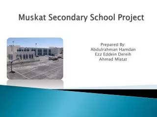
Graduation Project title: DESIGN OF YA’BAD SECONDARY BOYS SCHOOL
Main topics • Chapter one: Introduction • General • Materials • Loads • Codes and standards • Building structural system
Chapter One Introduction • General: The Ya'bad's secondary boys school is composed of one block, that consists of three floors with an area of 714 m2,and the total area of site is 3395 m2 . The ground floor includes class rooms, entrance hall, computer lab, art and crafts room and administration office. The first floor includes class rooms, teachers room and science lab. The second floor includes class rooms. The exterior walls are masonry that is formed of concrete, blocks and masonry stones. The interior walls are made of blocks.
Chapter One Introduction • Materials: Structural elements: • Concrete fc` = 240 kg/cm2 • Steel fy = 4200 kg/cm2. There are non structural materials that are used in the structure which are: • Blocks. • Masonry stone. • Tiles. • Filling under tiles.
Chapter One Introduction • Loads: There are two main types of loads: • Gravity loads: Live load: 0.3 ton/m2 (class room). 0.5 ton/ m2 (corridors and stairs) 0.5 ton/ m2 (halls and labs). 0.2 ton/m2 (roof). 2.5 ton/m2(stair roof) Dead load: it is consisting of own weight of the structure and any permanent components. The super imposed dead load is 0.5 ton/m2
Chapter One Introduction • Lateral load Seismic loads: The structure is located in Jenin area which is classified as zone 2B according to Palestine seismic zones. The UBC97 code seismic parameters are as follows: • The seismic zone factor, Z= 0.2. • The soil is very dense soil and soft rock, so the soil type is Sc. • The importance factor, I= 1.0 . • The ductility factor, R= 5.6. • The seismic coefficient, Ca=0.24. • The seismic coefficient, Cv=0.32.
Chapter One Introduction • Codes and Standards: • ACI 318-05 • UBC-97 • IBC 2009 • ASTM • Building Structural System: The slabs structural system is formed of one way ribbed slabs with drop beams. The beams are supported by separate columns which are the main vertical structural elements. The building structural system is formed of perimeter and stair case shear walls which is the main lateral forces resisting structural system, in addition to the building frames of beams and columns.
Main topics • Chapter two: Architectural And Environmental Analysis and Design • Architectural system • Environmental system
Chapter Two Architectural And Environmental Analysis and Design • Architectural system: • This building is composed of one block with three floors that includes inertial hall which make this building special compared with other schools. • The area of each floor is 714m2 while the total area of building is 3395 m2 . • A typical floor plan is shown in the following figure:
Chapter Two Architectural And Environmental Analysis and Design
Chapter Two Architectural And Environmental Analysis and Design • West elevation • North elevation
Chapter Two Architectural And Environmental Analysis and Design • South elevation • East elevation
Chapter Two Architectural And Environmental Analysis and Design • Environmental system • Environmental design is very important as much as the architectural and structural design, where the environmental analysis of the location is the first step that must be carried out by the engineer . • This analysis including the study of climatic factors such as solar radiation , temperature , wind and humidity in addition to thermal insulation used.
Chapter Two Architectural And Environmental Analysis and Design • Classification of the project area climate shown in this figure • This area located in the climatic zone-5 • The design temperature in winter 8.3 and in summer 33. • Relative humidity for (zone-five) is between (61.5-65.5) in summer and between (65.9-73.7) in winter • The average wind speed (7.9) km / h.
Chapter Two Architectural And Environmental Analysis and Design • Wind movement in the project area:
Chapter Two Architectural And Environmental Analysis and Design • Solar radiation in the project area:
Chapter Two Architectural And Environmental Analysis and Design • According to calculations the appropriate dimension of sun breaker shown in this figure.
Chapter Two Architectural And Environmental Analysis and Design • Thermal insulation: • The walls insulated by Polystyrene board in the middle with thermal conductivity 0.03 w/m.c and thickness 3cm and asphalt mix for ceiling with thickness 2cm as shown in this figure
Main topics • Chapter Three: Structural Analysis and Design • General • Slab systems and design • Beam design • Column design • Property/Stiffness Modification Factors • Structural Model Verification • Design of Slabs • Design of Beams • Design of Columns • Design of Footings • Design of stair and shear wall
Chapter ThreeStructural Analysis and Design • General: This chapter includes 1D & 3D modeling forthe project. The sections for slabs, beams, and columns are assumed and defined. Structural analysis comprises of set of physical and mathematical laws required to study and predict the behavior of structures under a given set of actions. The structural analysis of the model is aimed to determine the external reactions at the supports and the internal forces like bending moments, shear forces, and normal forces for the different members. These internal member forces are used to design the cross section of three elements.
Chapter ThreeStructural Analysis and Design • 1D Analysis and Design: • One way ribbed slabs : The deflection is the most important factor that controls the slab thickness, Minimum thickness of one way ribbed slab from ACI318-08 equals (L/18.5) for one end continuous.
Chapter ThreeStructural Analysis and Design • Beam design: Generally, concrete beams have a rectangular cross section since it is easy to be constructed in the field All beams must be able to resist shear, bending moments, and torsional stresses
Chapter ThreeStructural Analysis and Design • Column Design: Columns are structural elements used primarily to support axial compressive loads, that coming from slabs or beams above. Practically columns are subjected not to axial loads but also to moment from direct loading or end rotation.
Chapter ThreeStructural Analysis and Design Compatibility check:
Chapter ThreeStructural Analysis and Design Equilibrium Check : The total building dead load = 2084.8 ton The total building live load= 739.58 ton The total building super imposed dead load = 1426.992 ton From SAP2000: Total dead load= 2044.8 ton Total live load= 747.36 ton Total Sup. Imp. D.L = 1461.1 ton Error % in dead load = 2 %< 5% ok. Error % in live load = 1.0 %< 5% ok. Error % in super imposed D.L = 2.4 %< 5% ok.
Chapter ThreeStructural Analysis and Design Check Internal Forces: • Slabs & Beams: In order to check the internal forces in slabs and beams the bending moment values for number of spans will be obtained from SAP2000 and compared with the value of (ωL2\8), where ( ω= 1.2D + 1.6L). • Columns: As for columns the axial force values will be compared between SAP2000 and the manual method. - Where in any, the percentage error should not exceed 20-25 %
Chapter Three Structural Analysis and Design Footing: Footings are defined as the substructure whose function is to transmit safely the concentrated column or wall reactions to the soil stratum. footings which used in this project can be classified into the following types: 1) Isolated footing: they have rectangular, square, or circular shape. This type of footing is used for small loads, and/or large soil allowable bearing capacity. 2) Wall footing: it is a continuous footing along the length of the wall.
Chapter Three • Structural Analysis and Design
Chapter Three • Structural Analysis and Design Design Of Shear Walls: Shear walls are vertical elements of the horizontal force resisting system Shear walls should be located on each level of the structure, to form an effective box structure, equal length shear walls are preferred to be placed symmetrically on all exterior walls of the building. Shear walls must provide the necessary lateral strength to resist horizontal earthquake forces. When shear walls are strong enough, they will transfer these horizontal forces to the next element in the load path below them.
Chapter Three • Structural Analysis and Design Design Of Stairs: In this section stairs was designed, started by estimating the dead load and live load for this stairs, then performed and analyzed as simple model by SAP2000 program and took the deflection, shear and moment on it. Thickness of slab: • One end continuous t =L/24 • use 20 cm thickness
Chapter Three • Structural Analysis and Design • Section reinforcement
Main topics • Chapter four: Mechanical Design • Water Systems Design • drainage System design • Design of Fire Protection • HVAC System:(heating ,ventilation and air conditioning)
Chapter fourMechanical Design • Water Systems design: • Feeding water to buildings depends on the idea of the fall of water under the influence of gravity from roof tank and the pressure head which is developed. • There are three collectors 1,2 and 3 in the building ,every one has pipes that diameter calculated through the total number of fixture units that belong to every one and available pressure at the fixtures then by using a relevant tables diameter determined.
Chapter fourMechanical Design • So the diameters was found as following: • for main pipe from tank to collectors 1&2 is 2 ",and to collector 3 is 1.5 " , but for pipes from collectors to fixture is 3/4 ".
Chapter fourMechanical Design • drainage System design: • The diameter for drainage is determined according to the demand weight of fixtures by using the relevant tables • The diameter of the main stack =4 inch. • The size of the vent = 2 inch • For water closets the diameter of pipe = 4 inc • For lavatories the diameter of pipe = 2 inch. • For wall urinal the diameter of pipe = 2 inch. • For outside pipe to septic tank the diameter =5 inch. and slope • the total # of (FU)=149 so The capacity of septic tank is 18m3.
Chapter fourMechanical Design • Design of Fire Protection • Tow systems are used; sprinklers for rooms and fire house and fire extinguisher for corridor and hall.
Chapter fourMechanical Design • The number of sprinklers is determined according to rooms area and hazard degree of it by using this table: • So the sprinklers number for teacher &class rooms equal (4) and for art room equal (7 )and for headmaster, secretary and kitchen equal (1)
Chapter fourMechanical Design • HVAC system:(heating ,ventilation and air conditioning) • (HVAC) systems function is to provide healthy and comfortable interior conditions for occupants; well-designed, efficient systems do this with minimal non-renewable energy and cost and to achieve this the Polystyrene insulation used to help in this process.
Chapter fourMechanical Design • Design condition • This table shows the outside and inside design condition
Chapter fourMechanical Design • Heating load calculation • These equations that will we use in calculation • Rtotal=R1+R2+…+Rn • V vent = from tables by using rooms area and occupants • V inf =ASH*room volume • QL│vent =3.Vvent (wi –wo) • Vcirc=Qs cond+Qs ven/1.2(Tcirc –Ti) • Qtotal=Qs cond+Qsvent+Qdoestic • Qcond=A.U. ∆t • Qs│vent.=1.2.Vvent (Ti –To) • M cir =( Qs)cond + Qs) vent)/Cpw*(Ti– Td)
Chapter fourMechanical Design • To find Qcond=A.U. ∆t , U (over all heat transfer)is calculated for external & internal walls and for windows, doors, and floor and here an example for an external wall Rtotal=Ri+∑x/k +Ro U=1/R=1.14w/ m².c
Chapter fourMechanical Design • Then all the previous equations is applied on every room to determine the heat loss through walls, windows, doors and floor for each room • The sum of these values is the heating load • Q tot=Q rooms= 202400 W=202.4 KW • Q boiler =1.1*Qtotal = 222.64 Kw
Chapter fourMechanical Design • Pump selection • To select the pump for heating system • Pipe length = 65 m • Le =65*1.5 = 97.5 m • V=m' = Qtotal/(Cp∆T) =4.041 L/s • From fig select the correct one which is : • 200 pa/m < (∆p/Le)< 550 pa/m • Then type of pump is (HD3)
Chapter fourMechanical Design • cooling calculation: • for every room calculate • calculate load from people (from tables) • load from lighting= W * CLF (cooling load factor for lighting) • load from equipments=Qs=qs *clf • Q conv wall =U*A*CLTD corr for east,west,north andsouth walls where CLTD corr =(CLTD +LM )K+(25.5-Ti)+(To-29.4 ) all these terms are from tables


![[Title of Project]](https://cdn4.slideserve.com/168970/title-of-project-dt.jpg)