Download
1 / 6
60 likes | 147 Views
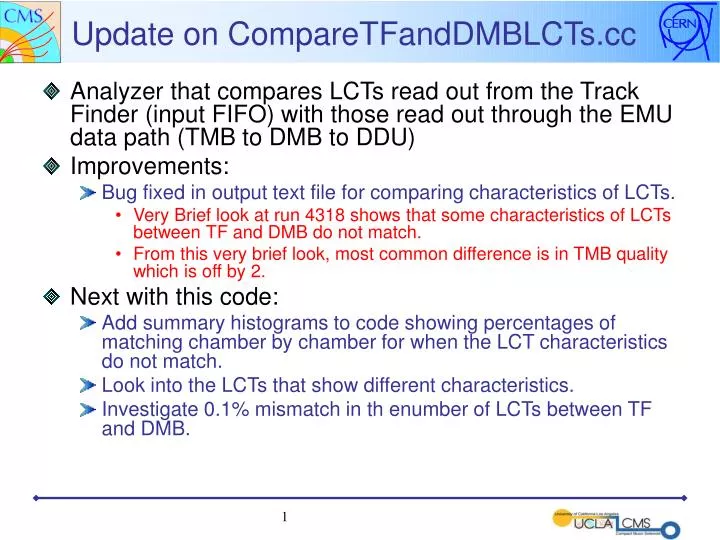
Update on CompareTFandDMBLCTs.cc. Analyzer that compares LCTs read out from the Track Finder (input FIFO) with those read out through the EMU data path (TMB to DMB to DDU) Improvements: Bug fixed in output text file for comparing characteristics of LCTs.

E N D
Update on CompareTFandDMBLCTs.cc • Analyzer that compares LCTs read out from the Track Finder (input FIFO) with those read out through the EMU data path (TMB to DMB to DDU) • Improvements: • Bug fixed in output text file for comparing characteristics of LCTs. • Very Brief look at run 4318 shows that some characteristics of LCTs between TF and DMB do not match. • From this very brief look, most common difference is in TMB quality which is off by 2. • Next with this code: • Add summary histograms to code showing percentages of matching chamber by chamber for when the LCT characteristics do not match. • Look into the LCTs that show different characteristics. • Investigate 0.1% mismatch in th enumber of LCTs between TF and DMB.
Update on L1TriggerEfficiency.cc • Analyzer finds LCT efficiencies using the overlap of chambers in phi • Improvements: • Added to the ability to cut on angle of segment with respect to CLCT pattern to investigate its affects on the chamber efficiency. • See next several slides.
Cut on Segment Angle wrt CLCT Pattern i.p. x • Method (part 1 of 2): • Project segment to layer 1 and layer 6 in chamber. • Get the global phi position of segment at both layers, Phi_1 and Phi_6. • Then the change in phi with respect to the change in z is: • Dphi/Dz = Phi_6 – Phi_1 • Note: • Note that in stations 3 and 4 the reverse of layers 6 through 1 wrt the ip is taken into account • When the chamber is near global_phi = 0 (not the case for the slice test chambers), it is also taken into account to substract 2*Pi from Dphi/Dz. z Φ1 Layer 1 Φ6 Layer 6 Top View of CSC (ME1 or ME2) muon
Cut on Segment Angle wrt CLCT Pattern i.p. x • Method (part 2 of 2): • Get the width of the strips (in radians) for the chamber that the segment is in • Then compare Dphi/Dz to a predetermined value of strip widths. • Start by cutting on di-strips with pattern 1 or 2 which ranges over 3 di-strips corresponding to 6 strip widths. Then continue comparing Dphi/Dz to a smaller value of strip widths. z Φ1 Layer 1 Φ6 Layer 6 Top View of CSC (ME1 or ME2) muon
Does this approach make sense? • 2-D histogram of Dphi/Dz vs. Strip Pattern for half-strips. • Note: • in ME2/2 and ME3/2 (where most of LCTs are located), strips are 2.33mrad • Strip Patterns 3-6 cross 2 half-strips (2.33mrad) • Strip Patterns 1 & 2 cross 3 half-strips (~4 mrad) • Strip Pattern 7 is straight (stays on same half-strip) ? This approach does seem to make sense.
Next • Apply this method to make cuts on segment angle in order to look at affect on chamber efficiencies. • Stay tuned……