Download
1 / 25
501 likes | 2k Views
123. DRIVE AXLE SHAFTS AND CV JOINTS. Figure 123-1 Typical rear-wheel-drive powertrain arrangement. The engine is mounted longitudinal (lengthwise). Figure 123-2 Typical front-wheel-drive powertrain arrangement. The engine is usually mounted transversely (sideways).

E N D
123 DRIVE AXLE SHAFTS AND CV JOINTS
Figure 123-1 Typical rear-wheel-drive powertrain arrangement. The engine is mounted longitudinal (lengthwise).
Figure 123-2 Typical front-wheel-drive powertrain arrangement. The engine is usually mounted transversely (sideways).
Figure 123-3 Typical driveshaft (also called a propeller shaft ). The driveshaft transfers engine power from the transmission to the differential.
Figure 123-4 This driveshaft failed because it had a slight dent caused by a rock. When engine torque was applied, the driveshaft collapsed, twisted, and then broke.
Figure 123-5 A center support bearing is used on many vehicles with long driveshafts such as long trucks.
Figure 123-6 Some driveshafts use rubber between an inner and outer housing to absorb vibrations and shocks to the driveline.
Figure 123-8 How the speed difference on the output of a typical U-joint varies with the speed and the angle of the U-joint. At the bottom of the chart, the input speed is a constant 1000 RPM, while the output speed varies from 900 RPM to 1100 RPM when the angle difference in the joint is only 10°. At the top part of the chart, the input speed is a constant 1000 RPM, yet the output speed varies from 700 to 1200 RPM when the angle difference in the joint is changed to 30°. (Courtesy of Dana Corporation)
Figure 123-9 The joint angle is the difference between the angles of the joint. (Courtesy of Dana Corporation)
Figure 123-10 The angle of this rear Cardan U-joint is noticeable.
Figure 123-12 A constant velocity (CV) joint can operate at high angles without a change in velocity (speed) because the joint design results in equal angles between input and output.
FREQUENTLY ASKED QUESTION: What Is a 1350-Series U-Joint? Most universal joints are available in sizes to best match the torque that they transmit. The larger the U-joint, the higher the amount of torque. Most U-joints are sized and rated by series numbers. See the accompanying chart for series numbers and sizes.Series Cap Overall TrunnionNumber Diameter Length Diameter (inches) (inches) (inches)1000 15/16 2 5/64 1/21100 15/16 2 13/64 1/21260/1270 1 1/16 2 31/32 19/321280 1 1/16 2 31/32 39/641310 1 1/16 2 31/32 21/321330 1 1/16 3 3/8 21/321350 1 3/16 3 3/8 49/641410 1 3/16 3 15/16 49/641480 1 3/8 3 7/8 57/64
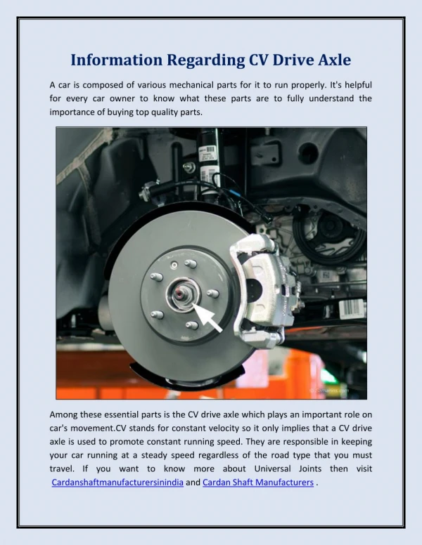
Figure 123-13 A Rzeppa fixed joint on a front-wheel-drive vehicle. This type of CV joint is commonly used at the wheel side of the drive axle shaft on a front-wheel-drive vehicle. This joint can operate at high angles to compensate for suspension travel and steering angle changes. (Courtesy of Dana Corporation)
Figure 123-14 The protective CV joint boot has been torn away on this vehicle and all of the grease has been thrown outward onto the brake and suspension parts. The driver of this vehicle noticed a “clicking” noise, especially when turning.
Figure 123-15 A tripod fixed joint. This type of joint is found on some Japanese vehicles. If the joint wears out, it is to be replaced with an entire drive axle shaft assembly.
Figure 123-16 The fixed outer joint is required to move in all directions because the wheels must turn for steering as well as move up and down during suspension movement. The inner joint has to be able to not only move up and down but also plunge in and out as the suspension moves up and down. (Courtesy of Dana Corporation)
Figure 123-17 Unequal-length driveshafts result in unequal drive axle shaft angles to the front drive wheels. This unequal angle sideto- side often results in a steering of the vehicle during acceleration called torque steer. By using an intermediate shaft, both drive axles are the same angle and the torque steer effect is reduced. (Courtesy of Dana Corporation)
Figure 123-18 A typical drive axle shaft with dampener weight.
Figure 123-19 A tripod joint is also called a tripot, tripode, or tulip design. (Courtesy of Dana Corporation)
FREQUENTLY ASKED QUESTION: What Is That Weight for on the Drive Axle Shaft? Some drive axle shafts are equipped with what looks like a balance weight. - SEE FIGURE 123–18 . It is actually a dampener weight used to dampen out certain drive line vibrations. The weight is not used on all vehicles and may or may not appear on the same vehicle depending on engine, transmission, and other options. The service technician should always try to replace a defective or worn drive axle shaft with the exact replacement. When replacing an entire drive axle shaft, the technician should always follow the manufacturer’s instructions regarding either transferring or not transferring the weight to the new shaft.
Figure 123-20 A cross-groove plunge joint is used on many German front-wheel-drive vehicles and as both inner and outer joints on the rear of vehicles that use an independent-type rear suspension. (Courtesy of Dana Corporation)
Figure 123-21 A cross-groove plunge joint is used on many German front-wheel-drive vehicles and as both inner and outer joints on the rear of vehicles that use an independent-type rear suspension. (Courtesy of Dana Corporation)
Figure 123-22 Getting the correct boot kit or parts from the parts store is more difficult on many Chrysler front-wheel-drive vehicles because Chrysler has used four different manufacturers for its axle shaft assemblies. (Courtesy of Dana Corporation)