Download
1 / 26
300 likes | 608 Views
Introduction to I/O. Computers communicate with the outside world via I/O devices Input devices supply computers with data to operate on Results of computations can be sent to output devices There are two main ingredients to I/O systems

E N D
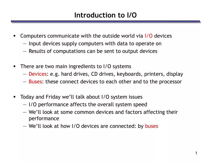
Introduction to I/O • Computers communicate with the outside world via I/O devices • Input devices supply computers with data to operate on • Results of computations can be sent to output devices • There are two main ingredients to I/O systems • Devices: e.g. hard drives, CD drives, keyboards, printers, display • Buses: these connect devices to each other and to the processor • Today and Friday we’ll talk about I/O system issues • I/O performance affects the overall system speed • We’ll look at some common devices and factors affecting their performance • We’ll look at how I/O devices are connected: by buses
I/O is slow! • How fast can a typical I/O device supply data to a computer? • A fast typist can enter 9-10 characters a second on a keyboard • Common local-area network (LAN) speeds go up to 100 Mbit/s, which is about 12.5MB/s • Today’s hard disks provide a lot of storage and transfer speeds around 40-60MB per second • Unfortunately, this is excruciatingly slow compared to modern processors and memory systems: • Modern CPUs can execute more than a billion instructions per second • Modern memory systems can provide 2-4 GB/s bandwidth • I/O performance has not increased as quickly as CPU performance, partially due to neglect and partially to physical limitations • This is changing, with faster networks, better I/O buses, RAID drive arrays, and other new technologies
Common I/O devices • Hard drives are almost a necessity these days, so their speed has a big impact on system performance: • they store programs, media, etc. • Virtual memory systems: hard disk acts as a large (but slow) part of main memory • Networks are also ubiquitous nowadays • access to data from around the world • Hard disks can act as a cache for network data! For example, web browsers often store local copies of recently viewed web pages • Many computing tasks are I/O-bound, and the speed of the input and output devices limits the overall system performance (Amdahl’s Law)
Hard drives • Figure 8.4 in the textbook shows the ugly guts of a hard disk • Data is stored on double-sided magnetic disks called platters • Each platter is arranged like a record, with many concentric tracks • Tracks are further divided into individual sectors, which are the basic unit of data transfer • Each surface has a read/write head like the arm on a record player, but all the heads are connected and move together • A 75GB IBM Deskstar has roughly: • 5 platters (10 surfaces), • 27,000 tracks per surface, • 512 sectors per track, and • 512 bytes per sector
Networks • When communicating over a network, data is broken into a collection of “packets” • Internet: • Each packet carries ~1kB of data • Packets are reassembled into the original message at the destination • It takes time for bits to travel across states, countries and oceans! ping www.uiuc.edu : time=0.275 ms ping www.stanford.edu: time=68.4 ms ping www.tu-berlin.de: time=140 ms
I/O Performance • There are two fundamental performance metrics for I/O systems: • Latency: the time taken for the smallest transfer (units = time) • This is a primary concern for programs that do many small dependent transfers • Bandwidth: the amount of data that can be transferred in unit time (units = bytes/time) • This is a primary concern for applications which transfer large amounts of data in big blocks • If you download large files over Kazaa, bandwidth will be the limiting factor
Back of the Envelope Calculation • Because data transmission can be pipelined, the total time to get data can be estimated as: Time = latency + transfer_size / bandwidth secbytes / (bytes/sec) Dominant term for small transfers Dominant term for large transfers latency
Accessing data on a hard disk • Accessing a sector on a track on a hard disk takes a lot of time! • Factors affecting latency: • Seek time measures the delay for the disk head to reach the track • A rotational delay accounts for the time to get to the right sector • Factors affecting bandwidth: • The transfer time is how long the actual data read or write takes. We usually assume that the disk can read/write as fast as it can spin. Thus, the transfer time is determined by the rotational speed (measured in revolutions per minute or RPM), which also determines the rotational delay
Estimating seek time • Manufacturers often report average seek times of 8-10ms • These times average the time to seek from any track to any other track • In practice, seek times are often much better • For example, if the head is already on or near the desired track, then seek time is much smaller. In other words, locality is important! • Actual average seek times are often just 2-3ms
Estimating rotational delay • Once the head is in place, we need to wait until the right sector is underneath the head • This may require as little as no time (reading consecutive sectors) or as much as a full rotation (just missed it) • On average, for random reads/writes, we can assume that the disk spins halfway on average • Rotational delay depends on how fast the disk platters spin: Average rotational delay = 0.5 rotations / rotations per minute • For example, a 5400 RPM disk has an average rotational delay of: 0.5 rotations / (5400 rotations/minute) = 5.55ms • The average latency is the sum of the average seek time and the average rotational delay
Estimating transfer time • Assume a disk has the following specifications • An average seek time of 11ms • A 5400 RPM rotational speed • A 10MB/s average transfer rate • How long does it take to read a random 1,024 byte sector? • The average rotational delay is 5.55ms • Thus, the average latency is 11 + 5.55 = 16.55ms • The transfer time will be about (1024 bytes / 10 MB/s) = 0.1ms • It thus takes 16.55ms + 0.1ms = 16.7ms to read a random sector • That’s 16,700,000 cycles for a 1GHz processor! • One possible measure of bandwidth would be the number of consecutive sectors that can be read in one second • each additional sector takes 0.1ms to read
Parallel I/O • Many hardware systems use parallelism for increased speed • Pipelined processors include extra hardware so they can execute multiple instructions simultaneously • Dividing memory into banks lets us access several words at once • A redundant array of inexpensive disks or RAID system allows access to several hard drives at once, for increased bandwidth • The picture below shows a single data file with fifteen sectors denoted A-O, which are “striped” across four disks • This is reminiscent of interleaved main memories from last week
System bus Memory Hard disks CD-ROM Network Display CPU Computer buses • Every computer has several small “networks” inside, called buses, to connect processors, memory, and I/O devices • The simplest kind of bus is linear, as shown below • All devices share the same bus • Only one device at a time may transfer data on the bus • Simple is not always good! • With many devices, there might be a lot of contention • The distance from one end of the bus to the other may also be relatively long, increasing latencies
Memory CPU Processor-memory bus I/O bus Hard disks CD-ROM Network Display Hierarchical buses • We could split the bus into different segments. • Since the CPU and memory need to communicate so often, a shorter and faster processor-memory bus can be dedicated to them • A separate I/O bus would connect the slower devices to the processor This bus is designed to be tolerant of adding additional devices
System bus (1) (3) Memory Hard disks CD-ROM Network Display CPU (2) Basic bus protocols • Although physically, our computer may have a hierarchy of buses (for performance), logically it behaves like a single bus • At the beginning of the semester we discussed how I/O reads and writes can be programmed like loads and stores, using addresses • Two devices might interact as follows: 1. An initiator sends an address and data over the bus to a target 2. The target processes the request by “reading” or “writing” data 3. The target sends a reply over the bus back to the initiator • The bus width limits the number of bits transferred per cycle
Control Address Data Memory Hard disks CD-ROM Network Display CPU What is the bus anyway? • A bus is just a bunch of wires which transmits three kinds of information • Control signals specify commands like “read” or “write” • The location on the device to read or write is the address • Finally, there is also the actual data being transferred • Some buses include separate control, address and data lines, so all of this information can be sent in one clock cycle
Control Address & Data CPU Memory Hard disks CD-ROM Network Display Multiplexed bus lines • Unfortunately, this could lead to many wires and wires cost money • Many buses transfer 32 to 64 bits of data at a time • Addresses are usually at least 32-bits long • Another common approach is to multiplex some lines • For example, we can use the same lines to send both the address and the data, one after the other • The drawback is that now it takes two cycles to transmit both pieces of information
Example bus problems • A CPU and memory share a 32-bit bus running at 100MHz • The memory needs 50ns to access a 64-bit value from one address • Questions generally ask about the latency or throughput: • How long does it take to read one address of memory? • How many random addresses can be read per second? • You need to find the total time for a single transaction: 1. It takes one cycle to send a 32-bit address to the memory 2. The memory needs 50ns, or 5 cycles, to read a 64-bit value 3. It takes two cycles to send 64 bits over a 32-bit wide bus • Then you can calculate latencies and throughputs: • The time to read from one address is eight cycles or 80ns • You can do 12.5 million reads per second, for an effective bandwidth of (12.5 x 10⁶ reads/second) x (8 bytes/read) = 100MB/s
Example Bus Problems, cont. • Assume the following system: • A CPU and memory share a 32-bit bus running at 100MHz • The memory needs 50ns to access a 64-bit value from one address For this system, a single read can be performed in eight cycles or 80ns for an effective bandwidth of (12.5 x 10⁶ reads/second) x (8 bytes/read) = 100MB/s A) If the memory was widened, such that 128-bit values could be read in 50ns, what is the new effective bandwidth? B) What is the bus utilization (fraction of cycles the bus is used) to achieve the above bandwidth? C) If utilization were 100% (achievable by adding additional memories), what effective bandwidth would be achieved?
Synchronous and asynchronous buses • A synchronous bus operates with a central clock signal • Bus transactions can be handled easily with finite state machines • However, the clock rate and bus length are inversely proportional; faster clocks mean less time for data to travel • This is one reason why PCs never have more than about five expansion slots • All devices on the bus must run at the same speed, even if they are capable of going faster • An asynchronous bus does not rely on clock signals • Bus transactions rely on complicated handshaking protocols so each device can determine when other ones are available or ready • On the other hand, the bus can be longer and individual devices can operate at different speeds • Many external buses like USB and Firewire are asynchronous
CPU North Bridge chip AGP port Video card Memory PCI bus South Bridge chip PCI slots Modem Sound card IDE controller Serial, parallel and USB ports Hard disks CD-ROM Buses in modern PCs
North Bridge chip 33 MHz PCI bus South Bridge chip PCI slots PCI • Peripheral Component Interconnect is a synchronous 32-bit bus running at 33MHz, although it can be extended to 64 bits and 66MHz • The maximum bandwidth is about 132 MB/s 33 million transfers/second x 4 bytes/transfer = 132MB/s • Cards in the motherboard PCI slots plug directly into the PCI bus. • Devices made for the older and slower ISA bus standard are connected via a “south bridge” controller chip, in a hierarchical manner
Frequencies • CPUs actually operate at two frequencies: • The internal frequency is the clock rate inside the CPU, which is what we’ve been talking about so far • The external frequency is the speed of the processor bus, which limits how fast the CPU can transfer data • The internal frequency is usually a multiple of the external bus speed • A 2.167 GHz Athlon XP sits on a 166 MHz bus (166 x 13) • A 2.66 GHz Pentium 4 might use a 133 MHz bus (133 x 20) • You may have seen the Pentium 4’s bus speed quoted at 533MHz. This is because the Pentium 4’s bus is “quad-pumped”, so that it transfers 4 data items every clock cycle. • Processor and Memory data rates far exceed PCI’s capabilities: • With an 8-byte wide “533 MHz” bus, the Pentium 4 achieves 4.3GB/s • A bank of 166MHz Double Data Rate (DDR-333) Memory achieves 2.7GB/s
CPU 64 32 North Bridge chip AGP port Video card Memory 2.7GB/s @ 133MHz 1.1GB/s @ 133MHz x 2 The North Bridge • To achieve the necessary bandwidths, a “frontside bus” is often dedicated to the CPU and main memory • “bus” is actually a bit of a misnomer as, in most systems, the interconnect consists of point-to-point links • the video card, which also need significant bandwidth, is also given a direct link to memory via the Accelerated Graphics Port (AGP) • All this CPU-memory traffic goes through the “north bridge” controller, which can get very hot (hence the little green heatsink) AGP 4x
External buses • External buses are provided to support the frequent plugging and un-plugging of devices • As a result their designs significantly differ from internal buses • Two modern external buses, Universal Serial Bus (USB) and FireWire, have the following (desirable) characteristics: • Plug-and-play standards allow devices to be configured with software, instead of flipping switches or setting jumpers • Hot plugging means that you don’t have to turn off a machine to add or remove a peripheral • The cable transmits power! No more power cables or extension cords • Serial links are used, so the cable and connectors are small
The Serial/Parallel conundrum • Why are modern external buses serial rather than parallel? • Generally, one would think that having more wires would increase bandwidth and reduce latency, right? • Yes, but only if they can be clocked at comparable frequencies • Two physical issues allow serial links to be clocked significantly faster: • On parallel interconnects, interference between the signal wires becomes a serious issue • Skew is also a problem; all of the bits in a parallel transfer could arrive at slightly different times • Serial links are being increasingly considered for internal buses: • Serial ATA is a new standard for hard drive interconnects • PCI-Express (aka 3GI/O) is a PCI bus replacement that uses serial links