Download

1 / 27
270 likes | 426 Views
The SuperKEKB Accelerator Status. M.Iwasaki (KEK) for the SuperKEKB accelerator group. KEKB to SuperKEKB : current status. KEKB operation finished at 9:00 am June 30, 2010 SuperKEKB budget is partially approved - Damping ring : 580M yen (~5.8M$) (FY2010)

E N D
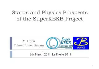
The SuperKEKB Accelerator Status M.Iwasaki (KEK) for the SuperKEKB accelerator group
KEKB to SuperKEKB: current status • KEKBoperation finished at 9:00 am June 30, 2010 • SuperKEKB budget is partially approved • - Damping ring : 580M yen (~5.8M$) (FY2010) • - Special budget “Very Advanced Research Support Program” • 1B yen (~100M$) (FY2010-2012) • Start construction(FY2010-2013)
KEKB to SuperKEKB KEKBaccelerator SuperKEKBaccelerator 1km • The KEKB B-factory in Japan • More than1ab-1 data / 11 years • The world highest luminosity • Will be upgraded toSuperKEKB • X40 higher luminosity
KEKB to SuperKEKB SuperKEKB 1036 40 times higher luminosity Next generation B-factories KEKB E.Kikutani / M. Masuzawa
Strategies for increasing Luminosity “Nano-Beam” scheme • Smallerby* • (2) Increase beam currents • (3) Increase xy Collision with very small spot-size beams
First proposed by P.Raimondi for SuperB • To increase luminosity, squeeze beams to nanometer scale • However, squeezing beams in stronger magnetic field • saturated by hourglass effect • → Enlarge crossing angle • and intersect bunches only at highly focused region Nano-Beam scheme Head-on collision Nano-beam scheme L ss overlap region = bunch length overlap region ~L Hourglass condition: βy*> ~σs Hourglass condition: βy*> ~L
Machine Design Parameters • Small beam size & high current to increase luminosity • Large crossing angle • Change beam energiesto solve the problem on LER short lifetime
Colliding bunches Belle II New IR e- 2.6 A New superconducting /permanent final focusing quads near the IP New beam pipe & bellows e+ 3.6 A KEKB to SuperKEKBHow to upgrade Replace short dipoles with longer ones (LER) Add / modify RF systems for higher beam current Low emittance positrons to inject Positron source Damping ring Redesign the lattices of HER & LER to squeeze the emittance New positron target / capture section TiN-coated beam pipe with antechambers Low emittance gun Low emittance electrons to inject To get x40 higher luminosity
Major items to upgrade - New Ante-chamber beam pipes Mitigation techniques for suppression of electron cloud. - New IR design New superconducting/permanent magnets around IP. Optimization of the compensation solenoid. Local Chromaticity correction sections for both rings. - New low emittance optics for both e+e- rings Replace dipoles & change the wiggler layout for positron ring - New low emittance beam injections New damping ring and target for positrons / New RF gun for electrons - Higher beam currents Add / modify the RF systems - Precise beam diagnostics and tunings More precise magnet setting ⇔power supplies.
New Ante-chamber beam ducts TiN-coated beam ducts with ante-chambers to suppress - Heating of components : HOM and SR - Electron cloud instability Y.Suetsugu Beam channel NEG pump SR channel Beam SR • Low SR power density • Less photoelectrons • in beam pipe • Low beam impedance Copper duct to withstand intense SR power
New Ante-chamber beam ducts In the place with less SR power, Aluminium beam ducts will be installed Y.Suetsugu Aluminum-alloy duct 110
New IR design based on the Nano-beam scheme New Final-Focusing system - Consists with superconducting and permanent magnets - Final focusing Q-magnets for each beam - Crossing angle 83 mrad to make the FF magnets close to IP e+ e- QC2RE QC2LP QC1RE QC1LP 41.5mrad Detector Solenoid axis IP QC2LE QC1RP QC1LE QC2RP
N.Ohuchi Prototype Q-magnet (collared) Prototype Q-magnet Superconducting Magnet R&D Test winding for QC1 corrector coil 7.8cm diameter Very compact superconducting magnets for final focusing system 3.8cm diameter
New IR design based on the Nano-beam scheme Optimization of the compensation solenoid Fringe fields by compensation solenoid increase the vertical emittance To solve this The field change must be as smooth as possible Solenoid field must be canceled within the IR region N. Ohuchi Compensation solenoid Bmax=3.4T Bmax=3.0T Solenoid field (compensation + detector)
New IR design based on the Nano-beam scheme • The new IP beam pipe design • - Crotched structures (Two FF Q-magnets in both sides) • 1cm radiusto avoid the resonant cavity structure • 4.5mm radius part to collimate SR • from FF Q-magnets • - Beam Position Monitors • are on the IP beam pipe K.Kanazawa BPM e+ e- IP M.Tobiyama
Replace short dipoles with longer ones for LER New low emittance lattice designAchieving low emittance with minimum change 0.89 m dipole 4 m dipole ~100 dipole magnets in the arc sections are replaced from 0.89 to 4 m dipoles. BELLE-II TDR
New low emittance lattice designAchieving low emittance with minimum change KEKB SuperKEKB Change the wiggler layout. Shorten wiggler period. BELLE-II TDR
New Positron Damping Ring We construct a positron damping ring for the very low emittance beam injection M.Kikuchi Electron cloud will be mitigated by TiN coating and solenoid windings. Founded for some components such as magnets.
We are here Milestone of SuperKEKB We will reach 50 ab-1 in 2020~2021. Integrated Luminosity (ab-1) SuperKEKB luminosity upgrade projection 9 month/year 20 days/month Commissioning starts mid of 2014 Peak Luminosity (cm-2s-1) Shutdown for upgrade Year Y. Ohnishi
Summary - KEKB will be upgraded to SuperKEKB - x40 higher peak luminosity (8x1035cm-2s-1) - x50 integrated luminosity(50 ab-1) within several years operation - SuperKEKB budget is partially approved - Start the SuperKEKB construction Plan to start the operation within FY2014 Please also see “Status and Prospects of SuperKEKB and Belle II” (Y.Ushiroda, 17:15 today @Salle 242A)
A1 gallery extension move to A1 cavity fabrication Construction Field measurement HP test e+ beam commissioning e- beam commissioning Commissioning at test stand align. Base plan Tunnel construction Fabrication Fabrication Other magnets HP&LLRF install Design Building construction cavity install cavity design Install Install B&Q mag. design/fabricate Install Power supplies R&D Design study MR construction Injector upgrade and DR construction schedule Jun. 24, 2010 FY2009 FY2010 FY2011 FY2012 FY2013 FY2014 e+ new matching & L-band acc. Linac RF-gun & laser system Damping Ring DR commissioning Magnets & Power supplies Beam pipes Monitors, Control RF System Tunnel & building Main Ring Beam operation MR commissioning K. Akai
Fabrication Conditioning Cabling / Check Building construction Design Design Alignment Layout change / Add stations / Cavity improvements Design & Fabrication Fabrication TiN coating Install Install Install Field measurement Install Design / Fabrication QCS fabrication QCS prototype Cooling system TiN coating Fabrication Install & test Test Remove magnets and beam pipes Base plates SuperKEKB Main Ring schedule Jun. 24, 2010 FY2009 FY2010 FY2011 FY2012 FY2013 FY2014 Beam operation MR commissioning Tunnel clear Beam pipes (LER_wiggler) Beam pipes (LER_arc) Beam pipes (HER) Magnets & Power supplies Beam monitors and Control RF system IR hardware Infrastructure K. Akai
Cost estimation 1 (Oku-Yen) = 1.1 M USD = 0.89 M EUR (as of 18 June, 2010) K. Akai
Next Generation B-factories IPAC10 SuperKEKB LER Crab waist Crab waist scheme for SuperKEKB NX 12.5 NY 12.25 NX 13.0 NY 12.25 K2 5.95 K2 5.95 • = 350 sec with crab sext off • = 40 sec with crab sext on Dynamic aperture not sufficient with a crab waist H. Koiso Apr. 2010
New Final-Focusing system New IR design based on the Nano-beam scheme Cryostat Anti solenoid-R QC1LP +corr. coil QC1RE +corr coil QC2RE PM QC2LP PM IP QC2LE PM QC2RP +corr. coil QC1LE +corr. coil QC1RP +corr. coil Anti solenoid-L Cryostat QC1RE N. Ohuchi
Next Generation B-factories IPAC10 IR design • Superconducting magnets • Leakage fields of superconducting magnets are • canceled by correction windings on the other • beam pipe • Warm bore • Permanent magnets • Cryostats can be made smaller • Assembly of vacuum chamber can be simpler • Vacuum pumps can be located nearer IP • R&D work needed for developing permanent magnets • Temperature dependence • Tunability (an additional magnet is needed when changing the energy) BELLE-II TDR N.Ohuchi, M.Tawada