Download
1 / 25
250 likes | 607 Views
MERLIN-DASH. Design and Analysis of Steel and Reinforced Concrete Straight Highway Bridge Systems. MERLIN-DASH Development. Began in 1975 Cooperative effort between Maryland State Highway & University of Maryland Basic program completed in 1978 Microcomputer version in 1985

E N D
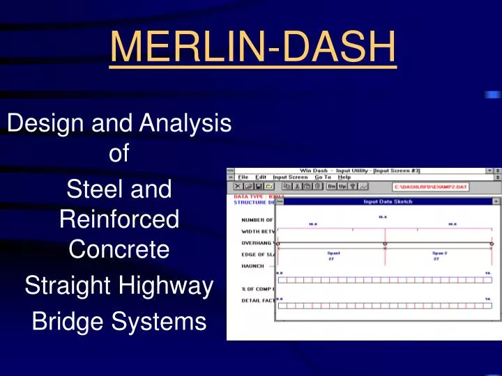
MERLIN-DASH Design and Analysis of Steel and Reinforced Concrete Straight Highway Bridge Systems
MERLIN-DASH Development • Began in 1975 • Cooperative effort between Maryland State Highway & University of Maryland • Basic program completed in 1978 • Microcomputer version in 1985 • FHWA DP-81 began in 1988 • SI version in 1994 • WINDOWS version in 1995 • LRFD version in 1996 • WINDOWS/NT & Network version in 1997
MERLIN-DASH Program Functions • Steel & Reinforced Concrete • English & SI Units • DL, SDL & LL + I • WSD, LFD & LRFD • Analysis, Design, Code Checking, Rating & Staging
New Alternations in LRFD • New Dynamic Load Allowance • New Distribution Factors • New HL-93 Truck • New Limit States • New Load Combinations • New Fatigue Consideration • New LRFD Specifications • New Design Considerations • New Rating
Auto Generation ofLRFD New Distribution Factors • By Force: Moment & Shear • By Geometry: Skewed & Non-skewed • By Zoning: Positive & Negative Moment Areas • By Limit State: Strength & Fatigue Limit States
LRFD Limit States Strength I rp1DC + rp2DW + 1.75(LL + I) Strength II rp1DC + rp2DW + 1.35(LL + I) Strength IV rp3(DC + DW) rp1 = 1.25 - 0.9, rp2 = 1.50 - 0.65, rp3= 1.5
LRFD Limit States (cont.) Service I (DC + DW) + (LL + I) Service II (DC + DW) + 1.3(LL + I) Fatigue 0.75(LL + I)
DASH Code Check Output • Web Depth and Thickness Ratio • Strength Category • Strength Bending Capacity • Strength Shear Capacity • Serviceability • Fatigue • Shear Connector (Fatigue) • Shear Connector (Strength) • Splice Design