Download
1 / 62
680 likes | 1.12k Views
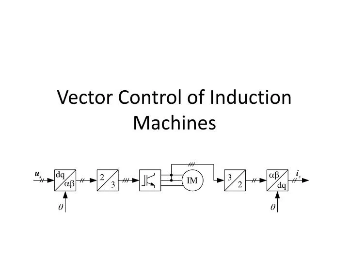
Vector Control of Induction Machines. Introduction. The traditional way to control the speed of induction motors is the V/Hz-control Low dynamic performance In applications like servo drives and rolling mills quick torque response is required. Desire to replace dc drives led to vector control

E N D
Introduction • The traditional way to control the speed of induction motors is the V/Hz-control • Low dynamic performance • In applications like servo drives and rolling mills quick torque response is required. • Desire to replace dc drives led to vector control • Braunschweig, Leonhard, Blaschke, Hasse,late 70-ies
What is vector control? • Vector control implies that an ac motor is forced to behave dynamically as a dc motor by the use of feedback control. • Always consider the stator frequency to be a variable quantity. • Think in synchronous coordinates.
Addition of a block for calculation of the transformation angle
The current is controlled in the d- and q-directions magnetization torque production
Rotor flux orientation • Difficult to find the transformation angle since the direction of the flux must be known • Flux measurement is required • Flux sensors (and fitting) are expensive and unreliable • Rotor position measurement does not tell the flux position • The solution is flux estimation
Rotor flux orientation using measured flux • Original method suggested by Blaschke • Requires flux sensors • Flux coordinates: aligned with the rotor flux linkage
The flux coordinate system is ”synchronous” only at steady-state. During transients the speed of the rotor flux and the stator voltage may differ considerably.
Rotor flux orientation using estimated flux • The rotor flux vector cannot be measured, only the airgap flux. • Flux sensors reduce the reliability • Flux sensors increase the cost • Therefore, it is better to estimate the rotor flux.
The "current model" in the stator reference frame(Direct Field Orientation)
The "current model" in synchronous coordinates (Indirect Field Orientation)
Remarks on indirect field orientation • Does not directly involve flux estimation (superscript f dropped) • Not ”flux coordinates” but ”synchronous coordinates” • Since the slip relation is used instead of flux estimation, the method is called indirect field orientation
Feedforward rotor flux orientation • Significantly reduced noise in the transformation angle • Fast current control is assumed (ref.value=measured value) • No state feedback => completely linear
The voltage model • The current model needs accurate values of the rotor time constant and rotor speed • The trend is to remove sensors for cost and reliability reasons • Simulate the stator voltage equation instead of the rotor voltage equation
Multiplication by yields Solve for
Stator flux orientation "Direct self-control" (DSC) schemes first suggested by Depenbrock, Takahashi, and Noguchi in the 1980s. At low frequencies the current model can be used together with:
Review of methods for current control • Hysteresis control • Stator frame PI control • Synchronous frame PI control
Hysteresis control(Tolerance band control) • Measure each line current and subtract from the reference. The result is fed to a comparator with hysteresis. • Pulse width modulation is achieved directly by the current control • The switching frequency is chosen by means of the width of the tolerance band. • No tuning is required. • Very quick response
Drawbacks of hysteresis control • The switching frequency is not constant. • The actual tolerance band is twice the chosen one. • Sometimes a series of fast switchings occur. • Suitable for analog implementation. Digital implementation requires a very high sampling frequency.
Stator frame PI control • Two controllers: one for the real axis and one for the imaginary axis • Cannot achieve zero steady-state error • Tracking a sinusoid means that steady-state is never reached in a true sense • Integral action is useless except at zero frequency
Synchronous frame PI control • In a synchronous reference frame the current is a dc quantity at steady-state. • Zero steay state error is possible. • Coordinate transformations necessary • Easily implemented on a DSP • Usually the best choice!
Design of synchronous frame PI controllers Remove cross-coupling