Download
1 / 31
340 likes | 508 Views
CCNA 1 Chapter 8 Routing Fundamentals and Subnets. By Your Name. Objectives. Routed protocol IP routing protocols The mechanics of subnetting. Routed Protocols Versus Routing Protocols. Routing protocols determine the path that routed protocols follow to their destinations.

E N D
CCNA 1 Chapter 8Routing Fundamentals and Subnets By Your Name
Objectives • Routed protocol • IP routing protocols • The mechanics of subnetting
Routed Protocols Versus Routing Protocols Routing protocols determine the path that routed protocols follow to their destinations.
IP as a Routed Protocol • IP is a connectionless, unreliable, best-effort delivery protocol. • As information flows down the layers of the OSI model; the data is processed at each layer. • IP accepts whatever data is passed down to it from the upper layers.
Packet Propagation Each router provides its services to support upper-layer functions.
Connection-Oriented Network Services A connection is established between the sender and the recipient before any data is transferred.
Anatomy of an IP Packet • Version • IP header length (HLEN) • Type-of-service • Total length • Identification • Flags • Fragment offset • Time-to-live • Protocol • Header checksum • Source address • Destination address • Options • Padding • Data
Routing Versus Switching • This distinction is routing and switching use different information in the process of moving data from source to destination.
Routed Versus Routing • A routed protocol: • Includes any network protocol suite that provides enough information in its network layer address to allow a router to forward it to the next device and ultimately to its destination. • Defines the format and use of the fields within a packet. • A routing protocol: • Provides processes for sharing route information. • Allows routers to communicate with other routers to update and maintain the routing tables.
Path Determination • Path determination enables a router to compare the destination address to the available routes in its routing table, and to select the best path.
Routing Tables • Routers keep track of the following: • Protocol type • Destination/next-hop associations • Routing metric • Outbound interfaces
Routing Algorithms and Metrics • Routing protocols have one or more of the following design goals: • Optimization • Simplicity and low overhead • Robustness and stability • Flexibility • Rapid convergence • Metrics most commonly used by routing protocols include the following: • Bandwidth • Delay • Load • Reliability • Hop count • Ticks • Cost
IGP and EGP • IGPs route data within an autonomous system. • EGPs route data between autonomous systems.
LinkState and Distance Vector • Examples of distance-vector protocols: • Routing Information Protocol (RIP) • Interior Gateway Routing Protocol (IGRP) • Enhanced IGRP (EIGRP) • Examples of link-state protocols: • Open Shortest Path First (OSPF) • Intermediate System-to-Intermediate System (IS-IS)
Routing Protocols • RIP • RIP v2 • IGRP • EIGRP • OSPF • IS-IS • BGP
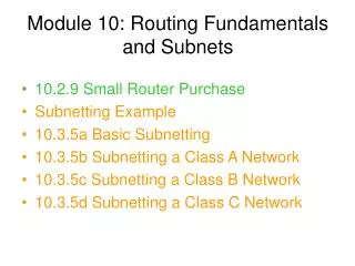
Subnetworks To create a subnet address, a network administrator borrows bits from the original host portion and designates them as the subnet field.
Subnet Mask • Determines which part of an IP address is the network field and which part is the host field. • Follow these steps to determine the subnet mask: 1. Express the subnetwork IP address in binary form. 2. Replace the network and subnet portion of the address with all 1s. 3. Replace the host portion of the address with all 0s. 4. Convert the binary expression back to dotted-decimal notation.
Subnet Mask Subnet mask in decimal = 255.255.240.0
Determining Subnet Mask Size Class B address with 8 bits borrowed for the subnet 130.5.2.144 (8 bits borrowed for subnetting) routes to subnet 130.5.2.0 rather than just to network 130.5.0.0.
Determining Subnet Mask Size Class C address 197.15.22.131 with a subnet mask of 255.255.255.224 (3 bits borrowed) The address 197.15.22.131 would be on the subnet 197.15.22.128.