Download
1 / 13
130 likes | 158 Views
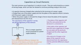
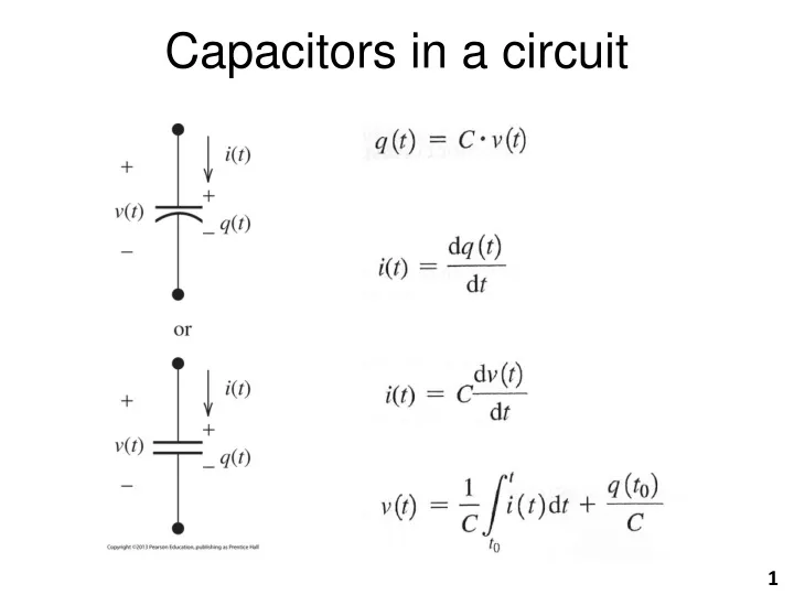
Capacitors in a circuit. 1. Example. C = 30 F. What if v(t) = 5A?. (A capacitor “looks like” an open circuit to DC). = 0. Let’s find the current through the following capacitor with v(t)=5 cos(2000 t)V. 2. Inductors.

E N D
Example C = 30 F What if v(t) = 5A? (A capacitor “looks like” an open circuit to DC) = 0 Let’s find the current through the following capacitor with v(t)=5 cos(2000t)V. 2
Inductors Inductor is a passive circuit element which stores energy in its magnetic field. It consists of a coil of wire wrapped around a core. 3
Inductance • Inductors are defined by their inductance (L) measured in henrys (H), where is the magnetic flux through the core of the inductor. 4
Inductors in a circuit = Li 5
Example L = 3 mH (An inductor “looks like” a short circuit to DC) = 0 1) 2) Let’s find the inductor voltage assuming • i(t) = 5 A, then • i(t) = 5 cos(2000 t) A. 6
10 20 mH Let’s find v in this circuit. 50 cos (100 t) V Apply KVL: You can either solve the differential equation, or transform the problem from the time domain to the frequency domain. Then the differential equation becomes a linear algebraic equation. 7
Im Time Domain: Re Circuit Component Time Domain Representation Frequency Domain (Phasor Representation) Transforming to the frequency domain is done using phasors. Start by writing each circuit quantity as a phasor. Argand Diagram Frequency Domain: M Sources M cos (t + ) VorA M/VorA Resistors R R/0 Inductors L H jL = L/90 Capacitors C F 1/(jC) = 1/(C)/-90 8
In the frequency domain, R, L, and C values are expressed in ohms. These ohmic values are called “impedances.” Impedance (Z) = Resistance (R) + j Reactance (X) Z = R + jX Ohm’s Law becomes: V = I Z 9
Let’s find i. 10 20 mH Vmax i = = 4.9/-11.3 Remember: j= 1/90 10/0 50/0 V jL = j (100)(2010-3) j 2 = 2/90 50 cos (100 t) V Apply KVL: 50/0 = (10/0) i + (2/90) i Solve: 50/0 = (10/0 + 2/90) i 50/0 = (10.2/11.3)i Transform back to time domain: i(t) = 4.9 cos (100t – 11.3) A 10
Now let’s find v. 10 20 mH 10/0 jL = j (100)(2010-3) j 2 = 2/90 50 cos (100 t) V 50/0 V i = 4.9/-11.3 i(t) = 4.9 cos (100t – 11.3) A Apply Ohm’s Law: v = i Z = (4.9/-11.3) (2/90) = 9.8/78.7 V Transform back to time domain: v(t) = 9.8 cos (100t + 78.7) V 11
Let’s find v and i. 10 k 10 F 50 cos (10t + 30) V 104/0 1/(jC) = 1/[(10)(1010-6)/-90] = 104/-90 50/30 V Apply KVL: 50/30 = 104/0i + 104/-90i 50/30 = (104/0 + 104/-90) i Solve: 50/30 = (1.414104/-45) i i =3.54/75 mA i(t) =3.54 cos (10t + 75) mA Ohm’s Law: v = (3.5410-3/75) (104/-90) = 35.4/-15 V v (t) =35.4 cos (10t – 15) V 12
Im Re Time Domain vs (t) = 50 cos (10t + 30) V i(t) = 3.54 cos (10t + 75) mA vc (t) = 35.4 cos (10t – 15) V vr (t) = 35.4 cos (10t + 75) V Frequency Domain vs = 50/30 V i= 3.54/75 mA vc = 35.4/– 15 V vr = 35.4/75 V 13