Download
1 / 44
440 likes | 620 Views
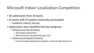
High-Precision Indoor Localization Using Spinning Beacons. Presenter Ho-lin Chang. Outline. Introduction Design Implementation Evaluation Conclusion and future Work. Introduction - Motivation. Warehouse. Security. Healthcare. Indoor location-based service.

E N D
High-Precision Indoor Localization Using Spinning Beacons Presenter Ho-lin Chang
Outline Introduction Design Implementation Evaluation Conclusion and future Work
Introduction- Motivation Warehouse Security Healthcare Indoor location-based service
Introduction – Related work WiFi UWB Ultrasound • Existed indoor localization technique • UWB • Ultrasound • WiFi
Introduction – Related work • UWB (Ubisense) • Accuracy: 10 ~ 20 cm • Time difference of arrival • Expensive specialized hardware (10,000 USD)
Introduction – Related work • Ultrasonic (Cricket) • Accuracy: 10 ~ 20 cm • Short range • Non-line of sight problem
Introduction – Related work • WiFi (Ekahau, RADAR) • RSS fingerprinting • Accuracy: 3 ~ 5m • Low cost • Offline training
Introduction – Contribution • Develop a novel localization system • Spinning beacon (RF) • Indoor environment • Sub-meter accuracy • 50%< 39 cm • 90%< 70 cm • Low cost • Low cost motes (100 USD) • Rotation motor
Doppler Angulation Doppler Angulation 2nd Doppler Angulation 3rd Doppler Angulation S S X S X R Localization The location of X
Design – Doppler Effect X f S vproject v
Design – When the beacon spins … Δf = 0 Hz Δf = -30 Hz Δf = 30 Hz Δf = 0 Hz X -30Hz 0Hz 0Hz v S 30Hz frequency Δf (t) = ? time
Design – Model the frequency waveform v(t) = (-ωr sinθ, ωr cosθ) y S : (r cosθ, r sinθ) X : (d cosα, d sinα) X d α r v(t) θ(t) = ωt+φ x S
Design – Doppler angulation y X α v(t) R β x S
Doppler Angulation Frequency observation 2nd Doppler Angulation S S 3rd Doppler Angulation X S X Time delay estimation R Localization centroid The location of X
Typical RF frequency is too high. • Radio Interferometry • “Radio InterferometricGeolocation” • [sensys ‘05] Doppler Angulation Frequency observation 2nd Doppler Angulation 3rd Doppler Angulation Time delay estimation 900 MHz B A 900 MHz + 500 Hz Localization centroid 500 Hz The location of X
Delay-and-compare method Doppler Angulation Frequency observation 2nd Doppler Angulation 3rd Doppler Angulation Time delay estimation Localization centroid The location of X
Implementation • Software • TinyOS 1.x • C/C++ • Hardware • Crossbow MICA2 • Rotational motor
Evaluation • Testbed • 國發所地下室停車場 • Three spinning beacons • 30 sample points (2m grid) • 10 position samples (300 samples) • 3 angles (900 angles) • Evaluation metrics • Positional error • Angular error • ParameterTuning
Evaluation – Angular accuracy 90% < 10 degrees 90% < 10 degrees 50% < 3 degrees 50% < 3 degrees
Evaluation – Positional accuracy 90% < 70cm 90% < 10 degrees 50% < 3 degrees 50% < 39cm
Evaluation – Parameter tuning • Data collection time • Rotational velocity • Interference frequency • Angulation filtering threshold • Minimumdistanceasaqualityindicator
Evaluation – Interference frequency Lower frequency estimation precision
System Limitation Track fast moving targets Rotational device
Conclusion • Develop a novel localization system • Spinning beacon • Indoor environment • Low cost • Sub-meter accuracy • 39cm / 70cm
Future Work • Reduce the localization latency • Reduce the routing time • Distributed version • Data compression • Track the fast moving targets
Design – Approximation r/d 0 0.1 0.3 0.5
Radio interferometry fA |fA + ΔfX - fB| |fA-fB| v X A B fB
Real Deployment S S A S R
Signal strength Time
FDOA (Frequency Difference of Arrival) I I I v X I I I • Each infrastructure perceives different Doppler shift. • Localize the target by different Doppler shifts
Maximum Doppler shift • f : 900 MHz • ω :2.5round/sec • r : 30 cm ~ 50 cm
Localization latency 0.3 ~ 1.5sec 8 ~ 10 sec 1st Doppler angulation Data collection Routing 2nd Doppler angulation Data collection Routing 3rd Doppler angulation Data collection Routing Localization Localization
Design – Model the frequency waveform v(t) = (-ωr sinθ, ωr cosθ, 0) y S : (r cosθ, r sinθ, 0) X : (d cosα, d sinα, h) X d α r v(t) θ(t) = ωt+φ x S