Download
1 / 10
100 likes | 220 Views
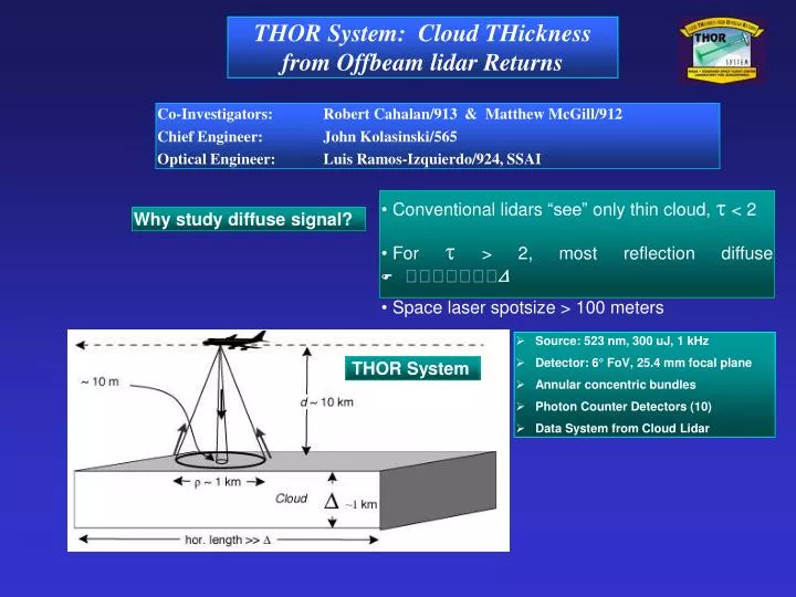
THOR System: Cloud THickness from Offbeam lidar Returns. Co-Investigators: Robert Cahalan/913 & Matthew McGill/912 Chief Engineer: John Kolasinski/565 Optical Engineer: Luis Ramos-Izquierdo/924, SSAI. Conventional lidars “see” only thin cloud, t < 2

E N D
THOR System: Cloud THickness from Offbeam lidar Returns Co-Investigators: Robert Cahalan/913 & Matthew McGill/912 Chief Engineer: John Kolasinski/565 Optical Engineer: Luis Ramos-Izquierdo/924, SSAI • Conventional lidars “see” only thin cloud, t < 2 • For t > 2, most reflection diffuse • Space laser spotsize > 100 meters Why study diffuse signal? • Source: 523 nm, 300 uJ, 1 kHz • Detector: 6° FoV, 25.4 mm focal plane • Annular concentric bundles • Photon Counter Detectors (10) • Data System from Cloud Lidar THOR System
THOR Proof of Concept • Real Clouds • Initial obs with Spinhirne Lidar • Signal detected in daytime out to 12° ! • No angular averaging, only time-average • Realistic thicknesses • Laboratory “Clouds” • “Cloud” properties reff , H) known • Realistic sizes, mfp ÷ 1000 ≈ 10 cm • Scale ~ Sqrt ( mfp* )
THOR Fiber Bundle Array 1. Micropulse lidar: 523 nm, 300 uJ, 1 kHz 2. GSFC-designed Telescope: 6° FoV, 25.4 mm f.p. 3. Annular bundles O.D. 2nconstant signal 4. Hamamatsu Photon-counting PMT Detectors 2 3 1 4 • 25.4 mm OD, roughly 250,000 fibers • ea. 50 mm OD (200 mm center) • Eight concentric rings, doubling in radius • Outer in 3 sectors, 50,000 fibers each. • Rings 3 - 7: • OD = 0.8, 1.6, 3.2, 6.4, 12.7 mm • Improved version: • >> concentricity • >> homogeneity
THOR System 3. Fiber Bundle 2. Telescope 4. PMT’s 1. 523 nm Lidar • Telescope designed at Goddard, built by Model Optics, MA • Bundle designed at Goddard, built by FiberOptic Systems, CA • Hamamatsu Detectors Data System - Cloud Lidar heritage 5. Data System Steerer, Expander • Optics aligned on collimator • First Msmts planned for March
Fiber Imaging on Collimator • 39 fibers in Ring 2, but ~150,000 in Ring 8 • Improvements planned under DDF • Goal : errors < 1% concentric, < 5% uniform
Data Acquisition • DAQ cards dev under contract for Cloud Lidar • Data system upgradeable for ER-2 • Timing goal: 15 m range gates
THOR “First Light” - March 8, 2001 8 7 6 5 4 3 2 1
THOR Road Map Time ActivityResources • Summer ‘01 Ground-based1 GSFC, Wallops • Spring ‘02 THOR Val on P32 Wallops ARM site • P3 at 30 K ft, cloud top below 5 K ft. • ARM MPL cloud base, 30 m resolution • Fall ‘03 THOR ER-2 Certification • Spring ‘03 THOR ER-2 Mission radar, A-band • Summer ‘03 co-fly AMSR on P33 Antarctic night • Possible MPL overflights with THOR on ground • Engineering model on P3, upgrade for ER2, or WB57, etc • Co-fly w/ Aqua val, Antarctica:’03 (J. Comiso)
THOR-Val Experiment at ARM/SGP • ItemResources • THOR Aircraft1 NASA-P3 • Mounting and labor Wallops • Dedicated P3 is $3.6 K per flight hour • 20 hours at DoE/ARM/SGP $72 K McConnell AFB, Wichita • P3 over ARM SGP2 MPL, Radar • Thickness accuracy dz ~ 30 m, dx ~ 500 m • Time on site 10 days • Suggested Timeframe Spring 2002 • Later: ER-2 Validation Activities Onboard: Cl.Radar, Cloud Lidar, A-band • Testing & Certification4 • Initial engineering flights on P3, upgrade 4 ER-2 • THOR Wallops may enable overflights • Co-fly w/ Aqua val, Antarctica: ‘02,’03 (Comiso) • ER-2 Cert requirements
THOR Challenge: Wide-angle Solar Filter • Detectors • Telescope 8” f/1.25, 6° FoV, ~42°@1” f.p. • Channel 1 d1 = 200 mm • Channels 2 –7 dn = 2 X dn-1 • Channels 8–10 120° sectors, d8 = 25.6 mm • PMTs Hamamatsu, single photon • Data System 215 mrad • Source • Type IV, Nd:YALO, 540 nm • Repetition Rate 1 kHz • Pulse Energy 170 mJ • Pulse Width 8 ns • Beam Waist 4 mm • Beam Divergence 215 mrad • Problem: How to filter Sun = 108*signal? Need ±0.01 nm for 6° FoV. • Dispersion filter selects wavelength by selecting angle. • Requires collimated beam. • Faraday cell rotates polarization plane to select wavelength. • Faraday cell successfully used on ground. • Air/satellite use of magnetic fields problematic due to shielding and power. • In space FoV ~ 1 milli radian. • Wide angle solar filters might use other polarization effects, e.g. birefringence. • Wideangle filters have other applications, e.g. filter out Earth in communications.