Download
1 / 26
500 likes | 1.4k Views
Magnetic Sensors and Magnetic Actuators. Digital Compass Solution Combines a two axis MR Magnetic Sensors in order to detect the magnetic field. Use in wireless phone, vehicle compassing and antenna Positioning. GMR head Structure. February 2005.

E N D
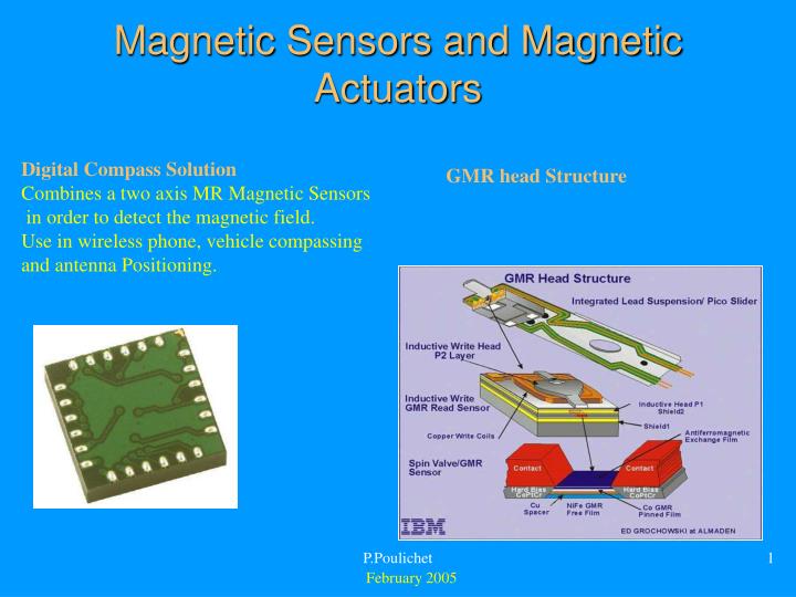
Magnetic Sensors and Magnetic Actuators Digital Compass Solution Combines a two axis MR Magnetic Sensors in order to detect the magnetic field. Use in wireless phone, vehicle compassing and antenna Positioning. GMR head Structure P.Poulichet February 2005
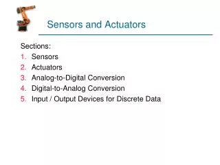
Different types of Magnetic Sensors and Magnetic Actuators • Magnetic Sensors • Inductive sensor • Hall sensor • Magnetoresistance (MR) • Giant Magnetoresistance (GMR) • FluxGate • Magnetic Actuators • Microinductance • Actuators P.Poulichet
Units Magnetic Induction: Tesla: T Magnetic Induction: Gauss = 10-4 T Magnetic field: A.m-1. Magnetic Field Oersted: 1 A.m-1 = 4. pi.10-3 Oe Magnetic flux: 1T.m2 = 1 wb Permeability: 4.pi.10-7 P.Poulichet
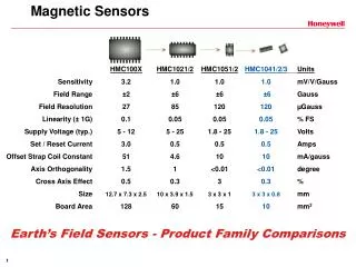
Measurement Magnetic Field Range (mT) Sensitivity (nT) Frequency Range (Hz) Applications Inductive Effect 10-10 à 106 Depend of applications 0.1 to 107 Detection of variable Magnetic Field Hall effect 0.1 à 3.104 100 0 to 100 M Ratiometric linear sensor (Current sensor) MR And GMR 10-3 à 5 10 0 to 10 M More sensitive than Hall Effect but less linear (Compasses) « Fluxgate » 10-4 à 0.5 0.1 0 to 10 k Vectorial Magnetometer (compasses) Characteristics of Magnetic Sensors P.Poulichet
Inductive Sensors Inductance to generate or to measure a magnetic field Model of the inductor NDE (Non Destructive Evaluation) Electroplating • Applications: • NMR (Nuclear Magnetic Resonance) • NDE, Isolator ADuM1100 P.Poulichet
Hall Sensors: Principle Magnetic effect in a long sample l>>w Drift velocity mobility carriers density Current density Magnetic Force The magnetic force push carriers toward the upper edge of the strips. Electricity behaves somewhat like an incompressible fluid. It reacts by developing an electric field, the Hall field that counterbalances exactly the magnetic pressure exactly. P.Poulichet
Hall Sensors The Hall electric field is: The Hall voltage is: Hall angle: Hall coefficient: The Hall voltage depend of: P.Poulichet
InAs InSb AsGa n (cm2/Vs) 33000 78000 8500 p (cm2/Vs) 460 750 400 Hall Sensors: Optimization 1 In order to increase the sensitivity, these materials are use: Different sorts of errors for Hall sensors: • Scattering of the sensitivity of the Hall voltage • Dependence of the Hall voltage with the temperature • Inductive effect • Offset, linearity P.Poulichet
Linearity Offset Inductive effect Hall Sensors: Optimization 2 Magnetic sensor placed near the electronic in order to correct the errors of the Hall Sensor. P.Poulichet
Reference Magnetic Field Range (T) offset Voff Sensitivity S mV.mT-1 For 1 degree For 1 degree frequency cut-off Price (euros) 1 piece KSY14 Siemens non defined 15 mV 1.05 à 1.6 0.03% 0.3% 0.7% Above 1 MHz 6 UGN3503 Allegro With electronic non defined 2.5 V 7.5 à 17.2 0.05% pour 0.05 mT stable 2% 23 KHz 7 SS495A1 Honeywell With electronic -0.06 to 0.06 2.5V 31.25 3% 0.03% 0.04% 1% 50 KHz 7 SS94A2 Honeywell With electronic -0.05 to 0.05 4V 5 2% 0.02% 0.02% 0.8% 100 KHz 30 Hall Sensors: Applications P.Poulichet
Magnetic effect in a short sample l<<w Magnetoresistance: Principle Lorentz Force Current density As, Jp(B) are present on the two sides of this equation, we can simplified: Jp(0) and B are perpendicular The path of the current in the sample depend of the external magnetic field. So the resistance depend of the magnetic field. P.Poulichet
The term show that the resistivity depend of B. Magnetoresistance Dependence of R/R0 function of B This type of sensor are not largely use because The characteristics of the magnetoresistance anisotropic are better. InSb :Antimoine d’Indium NiSb : Antimoine de Nickel P.Poulichet
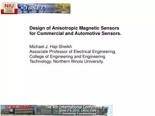
Magnetoresistance Anisotropic The anisotropy is obtained during the fabrication of the material. It is applied a magnetic that caused a preferred path for the magnetic field. During the step of sputtering on a thin film like Permalloy (FeNi 20% 80%, a magnetic field is applied and this introduce a easy path. This magnetic field introduce a easy axe and a magnetization of the thin Film. M: Magnetization I: Current H: External magnetic field We will show that the resistance depend of the angle j and q. P.Poulichet
AMR In order to simplify, we suppose that H is applied in the direction of Hy. and If I is align with the easy axis: = -. So, • The resistance decrease with the magnetic field. • The magnetic sensor is not linear. • It is also impossible to determine the sign of the magnetic field. P.Poulichet
AMR with Barber poles If I is align at 45 degrees: 45 = + P.Poulichet
Reference Magnetic field range (T) Sensitivity S:mV.mT-1 Supplied with 5 V for 1 degree Bridge Resistance KMZ10A Philips -0.625 mT to +0.625 mT 64 -0.15 %.°C-1 1.3 K KMZ10C Philips -3.75 mT to +3.75 mT 6 -0.15 %.°C-1 1.7 K AMR: Realization KMZ10A P.Poulichet
GMR: Principle Sandwich with one ferromagnetic layer and one non magnetic layer. FeCr, FeNiAg, FeNiCu with thickness Fe = 30 A et Cr = 9 A Without B With B P.Poulichet
GMR: Principle Without B With B P.Poulichet
Reference Range (T) Offset Voff Sensitivity mV.mT-1 supplied with 1V Linearity Resistance k NVS5B15 1,5m 0 4mV 30 à 44 2% 5 20% NVS5B50 5m 0 4mV 9 à 13 2% 5 20% NVS5B100 10m 0 4mV 4,5 à 6,5 2% 5 20% GMR P.Poulichet Realization (NVE)
Size Resolution Sensitivity Anisotropic Magnetoresistance (AMR) 0.5%/Oe 0.1 Oe 1-100 µm Giant Magnetoresistance (GMR) 0.01 Oe 1%/Oe 1-100 µm Wire FeCoNi electroplated (GMI) 500%/Oe 1-2 mm 0.000001 Oe Applications of AMR and GMR Measurement of current Detection of the speed P.Poulichet
FluxGate: Principle The first winding is used to saturate the magnetic Material. When the magnetic material is saturate, there is no voltage across the second winding. Measurement of delay introduce on the voltage across the second winding will be help to determine the value of the magnetic filed. When there is no magnetic field, the gap between the pulse is constant. When a magnetic field is applied, the gap between the two pulses are different. P.Poulichet
Configuration of the windings FluxGate: Realization The fluxgate is very sensitive. The realization is complex but magnetic sensors with low sensitivity have good perspective. P.Poulichet
Principle: Use the skin effect Magneto Impedance: MI A current in a wire cause that the current density is concentrate at the periphery of the wire. So the impedance of the wire increase with the frequency. A external magnetic field cause also a dependence of the impedance with the magnetic field. The purpose is to polarize the wire at a frequency and the external magnetic field cause a variation of the impedance. Characteristics Polarization at 10 MHz. Range of B from nT to µT. Sandwich of Layers: FeCoSiB: 40 µm thickness. Wire: CoFe: 30 µm diameter. P.Poulichet
Magnetic Actuator MAGMAS: Magnetic micro actuator and system A micro Inductance is used to generate a magnetic field. This magnetic field act on a magnetic layer in order to develop a force. Micro Inductance Conductor (Al, Cu) deposed on a substrate glass or Si. The size, the number of turns give a inductance value. The thickness of the conductor must be important. The conductor need to be deposed by electroplating in a molding. Current density increase with the reduction of the size of the conductor (1000 A.mm-2 for a wire with a µm dimension). Magnetic material Permalloy FeNi electroplated. Magnet The magnet is placed under the micro inductance. It is glued or electroplated. P.Poulichet
2D Optical Switch Array for Optical Routing A mirror move when a current is applied on the micro inductance. It reflect the light transmit with the optics fiber. Under the membrane, the permalloy is electroplated. Under the coil, a magnet is placed. A pulse in the coil shift the mirror. When the signal is interrupted, the mirror stay in position. When another pulse is applied on the coil, the mirror move. P.Poulichet
Bibliographie About Hall Sensors: Hall Effect Devices RS POPOVICS (Library). About GMR: Magnetic Multilayers and Giant Magneto-resistance, Springer, Surface Sciences (Library). P.Poulichet