Download
1 / 102
2.1k likes | 3.42k Views
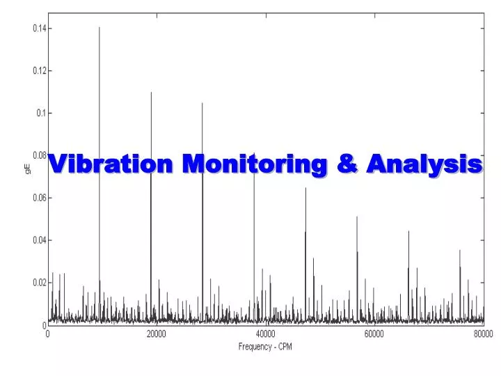
Vibration Monitoring & Analysis. Vibration Monitoring. What is Vibration ? It is motion of mechanical parts back and forth from its position of rest /neutral position. Vibration Monitoring. What causes Vibration ? Induced Force & Freedom for Movement. Vibration Monitoring.

E N D
Vibration Monitoring What is Vibration ? It is motion of mechanical parts back and forth from its position of rest /neutral position.
Vibration Monitoring What causes Vibration ? Induced Force & Freedom for Movement
Vibration Monitoring • Harmful Effects of Excess vibration • Increased load on BRGs: Reduced BRG Life • Higher Forces on Mountings: • Foundation Loosening and Damage of Support Structure • Increased Stresses of M/c : Risk of fatigue • components
Vibration Monitoring • Harmful Effects of Excess vibration • Decreased Equipment efficiency. • Reduced Output Quality. • Increased Maintenance Cost due to more Component Failures and Unplanned Operations • Unsafe Operating Environment
Vibration MonitoringProblem Identifications • Unbalance • Misalignment • Mechanical Looseness • Antifriction / Sleeve Bearing Defects • Gear Defects
Vibration MonitoringProblem Identifications • Belt Defects • Impeller / Blade Defects • Bent Shaft • Electrical Problems • Resonance
Vibration Monitoring • Fundamental Realities • All Machines vibrate. • An increase in vibration level is a sign of trouble & amplitude of Vibration depends on the extent of defect in the machinery components • Each trouble will create vibration with different characteristics
Period(T) (1 complete cycle) VIBRATION FUNDAMENTALS 90 Upper Limit Neutral Position 180 TIME Lower Limit 270
Characteristics of Vibration • Vibration characteristics are • Amplitude • Frequency Hz or CPM • Phase Angle or clock face Displacement Velocity Acceleration
Parameter Selection • Frequency sensitivity
Vibration Monitoring Displacement Velocity Acceleration
FFTFAST FOURIER TRANSFORM. • THE PROCESS OF TRANSFORMING TIME DOMAIN SIGNAL TO FREQUENCY DOMAIN. • THE TIME DOMAIN SIGNAL MUST FIRST BE SAMPLED AND DIGITIZED.
Rolling Imbalance Element Bearing Gearmesh Coupling chatter Resultant Complex Waveform Time Time Domain - overall data is the sum of all exciting and reacting forces
Spectrum Analysis Enables precise evaluation of machinery condition and prediction
Fmax, LINES, AVERAGES. • Fmax REPRESENTS THE MAXIMUM FREQUENCY RANGE IN CPM OR HZ TO BE SCANNED BY THE INSTRUMENT. • Fmax SHOULD NOT BE SET TOO HIGH SO THAT THE RESOLUTION AND ACCURACY SUFFERS OR IT SHOULD NOT BE TOO LOW SO THAT WE MISS SOME IMPORTANT HIGH FREQUENCIES.
GUIDELINES FOR SETTING Fmax. • FOR MACHINES HAVING ANTI-FRICTION BEARINGS:- Fmax = 60 x RPM • FOR MACHINES HAVING SLEEVE BEARINGS:- Fmax = 20 x RPM • FOR GEAR BOXES:- Fmax = 3.25 x GMF
LINES OF RESOLUTION • THE RESOLUTION IS THE NUMBER OF LINES OR CELLS WHICH ARE USED TO CALCULATE AND DISPLAY THE FREQUENCY SPECTRUM. • THE BANDWIDTH CAN BE CALCULATED BY DIVIDING Fmax BY THE LINES OF RESOLUTION. • THE GREATER THE NUMBER OF LINES , THE BETTER IS THE ACCURACY.
FREQUENCY RESOLUTION F max Bandwidth = total lines of resolution total lines of resolution lines or bins or cells of resolution Amplitude Fmax Frequency
Spectrum Data Collection Time • FFT Calculation Time = Time to calculate FFT from Time Waveform [assuming no overlap processing] (60) ( #FFT Lines) (#Averages) FFT Calculation Time = Frequency Span Where: #FFT = Number of FFT Lines or Bins in Spectrum # Averages = Number of Averages Frequency Span measured in CPM
OVERALL VIBRATION Total summation of all the vibration,with no regard to any particular frequency.
OVERALL VIBRATION Overall vibration is the total vibration energy measured within a frequency range. Measuring the “overall” vibration of a machine or component, a rotor in relation to a machine, or the structure of a machine, and comparing the overall measurement to its normal value (norm) indicates the current health of the machine. A higher than normal overall vibration reading indicates that “something” is causing the machine or component to vibrate more.
Overall Vibration Total summation of all the vibration,with no regard to any particular frequency. OA = OA=Overall level of Vibration Spectrum , Ai = Amplitude of each FFT line n = No. of FFT Lines of resolution , NBF= Noise Bandwidth for Window chosen 2 2 2 A1 + A2 + ………………………+An NBF
NOTE: Don’t be concerned about the math, the condition monitoring instrument calculates the value. What’s important to remember is when comparing overall vibration signals, it is imperative that both signals be measured on the same frequency range and with the same scale factors.
What is Phase? • The position of a vibrating part at a given instant with reference to a fixed point or another vibrating part. • The part of a vibration cycle through which one part or object has moved relative to another part. • The unit of phase is degree where one complete cycle of vibration is 360 degrees.
Phase is a measurement, not a processing method. Phase measures the angular difference between a known mark on a rotating shaft and the shaft’s vibration signal. This relationship provides valuable information on vibration amplitude levels,shaft orbit, and shaft position and is very useful for balancing and analysis purposes.
Additional Illustration on Phase
PHASE AN ILLUSTRATION 32 Micron 10 degrees 30 Micron 10 degrees Shaft centre line moves up and down in a planer fashion
PHASE AN ILLUSTRATION 32 Micron 190 degrees 30 Micron 10 degrees Shaft center line moves up and down in a rocking fashion
MACHINE TRAIN MISALIGNMENT TURBINE G/B HP COMP LP COMP AXIAL PHASE (degrees) 0 5 15 18 198 215 10 12 22 24 210 220 12 10 20 22 208 218 8 6 16 20 200 210 Note: All phase readings corrected for pickup direction
Phase application C B A A 5 Microns, 10 degrees B 7 Microns, 12 degrees C 25 Microns, 175 degrees Bolt at C is loose
Vibration Analysis of Common Problems
Vibration AnalysisUnbalance • Amplitude proportional to the amount of unbalance • Vibration high normally in radial direction (may be also in axial direction incase of overhung and flexible rotors ). • 1* RPM vibration is greater than 80% (normally) of the overall reading.
Vibration AnalysisUnbalance • Horizontal and vertical 1* RPM amplitude should be nearly same, although it also depends on system rigidity on the particular direction. • Other frequency peaks may be less than 5% of the 1*RPM amplitude • Phase shift of 90 deg. When sensor moves from horizontal to vertical.
UNBALANCE • Operating conditions such as load, flow condition and temperature effect unbalance • Balance under normal operating conditions • Changes in track and pitch angle of fan blades can result in “Aerodynamic Unbalance”
MISALIGNMENT • BIGGEST PROBLEM INITIALLY • Operating temperature can affect alignment • Machines aligned cold can go out when warm • Bases or foundations can settle • Grouting can shrink or deteriorate • Increases energy demands
MISALIGNMENT • Forces shared by driver and driven (not localized) • Level of misalignment severity is determined by the machines ability to withstand the misalignment • If coupling is stronger than bearing the bearing can fail with little damage to the coupling
Three Types of Misalignment • Combination (most common) • Angular • Parallel or Offset
General Characteristics Of Misalignment • Radial vibration is highly directional • 1X, 2x, and 3x running speed depending on type and extent of misalignment • Angular 1x rpm axial • Parallel 2x rpm radial (H & V) • Combination 1,2,3x rpm radial and axial
Vibration AnalysisMisalignment Angular Misalignment • High axial vibration ( Greater than 50% of the radial vibration) • 1* , 2*, 3* RPM normally high. • 180 deg. Out of phase across the coupling
Angular Misalignment • Produces predominant 1x rpm component • Marked by 180 degree phase shift across the coupling in the axial direction
Vibration AnalysisMisalignment Off-Set Misalignment • High Axial vibration. Also shows high radial vibrations. • 1*, 2*, 3* RPM high. 2* often larger than 1* • In case of severe misalignment, much high harmonics (4* - 8*) or even a whole series of high frequency harmonics will be generated. • 180 deg. Out of phase across coupling
Parallel Or Offset Misalignment • Produces a predominant 2x rpm peak in the spectrum • Marked by 180 degree phase shift across the coupling in the radial direction.