Download
1 / 15
150 likes | 325 Views
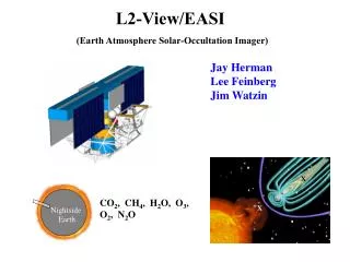
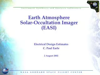
Earth Atmosphere Solar-Occultation Imager. Thermal Rob Chalmers 2 August 2002. Thermal Requirements. Provide means of controlling two InSb CCDs to 40-50 K. Maintain other parts of instrument optical systems at approximately room temperature.

E N D
Earth AtmosphereSolar-Occultation Imager Thermal Rob Chalmers 2 August 2002
Thermal Requirements • Provide means of controlling two InSb CCDs to 40-50 K. • Maintain other parts of instrument optical systems at approximately room temperature. • Provide thermal control of instrument truss structure (temperature stability and uniformity) so that thermally-induced distortions remain within acceptable limits. • EASI must survive transit to L2 (full sun environment). Since the thermal impact on the spacecraft during this phase of the mission will almost certainly be more profound than it is on the instrument, it is recommended that this be addressed during the upcoming IMDC study.
EASI Thermal Control Concept Focal planes cold-sunk to radiant cooler having nearly hemispheric view to deep space. MLI blankets entirely cover truss (except telescope apertures), decoupling the structure from variations in the external thermal environment. Will require some heater control. Neutral density filters over telescope apertures greatly reduce heat input entering telescope optics.
Detector Thermal Control • To meet performance requirements, the proposed 1K x 1K InSb CCDs must operate at TBR K (40-60K assumed). Total dissipation: approximately 10-16 mW. • A passive cooling system (cold finger leading to radiative cooler on anti-sun side of truss) is proposed. However, it is recognized that there are some uncertainties in developing a radiative cooler that will provide adequate cooling at the desired temperature (60 K is merely difficult, but 40 K may prove impossible). • If a purely-passive design is found to be unworkable, more complex (and expensive) mechanical cryocoolers are available. • Precise CCD temperature stability (if required) can be achieved via small heaters and electronic temperature controllers.
Passive Radiative Cooling at Low Temperatures:Ideal Heat Rejection vs. Temperature
Passive Radiative Cooling at Low Temperatures:40 K Poses A Real Challenge • Considerations: • Radiative coolers are highly-engineered, “one-of-a-kind” contraptions requiring meticulous modeling and analysis. • Detector power dissipation (10-15 milliwatts for EASI) is typically only a small fraction of the total load on a low-temperature cooler; parasitic heat loads from nearby objects force the area of the “cold patch” to be many times larger than might be otherwise expected. • The design of a radiative cooler is much more straightforward if it can be provided a hemispherical view of cold space (less need for highly-polished, contamination-sensitive shields). L2 provides an ideal thermal environment, and the cooler’s field of view should be jealously protected. • The cold patch of the EASI cooler must be located as close as possible to the detector focal planes. The length of the cold finger can quickly overload the cooler with unwanted parasitics.
Passive Radiative Cooling at Low Temperatures:A Survey of Several Missions • Some Passive Radiative Coolers (Past/Present/Future): • CIRS on Cassini (<20 mW focal planes at 80 K, two stages, deep space) • SIRTF (launch in 2003, cryostat outer shell passively(?) cooled to 35-40 K, driftaway orbit) • HFI on Planck (launch in 2007, 50/60 K, multiple stages, L2) • NIMS on Galileo (InSb detectors at 64 K, single stage, deep space) • MODIS on Terra and Aqua (136 mW at 83 K, 3 stage, LEO, area of cold side approximately 6 ft2, about $2M) • ETM+ on Landsat 7 (90 K, at least $750K) • VIRS on TRMM (22 mW at 107-122 K, modified ADL 101 design, LEO) • TGRS on GGS/WIND (Ge detector at 85 K, 2 stage, elliptical earth orbit) • MAP (entire instrument passively cooled to 80-90 K, L2) • DIRBE on COBE (55 K following depletion of cryogen, sun synchronous LEO) ? - SIRTF cryostat surrounded by several vapor cooled shields
A Passive Radiative Cooler for EASI • Based on past missions which have incorporated passive cooler designs, the cost of a cooler for EASI may be in the neighborhood of $1-2M. • Because of the excellent space view afforded by the L2 environment, the EASI cooler would not require the complex shielding found in LEO coolers. But… • Because of the low temperature requirement (40K), the EASI cooler will require a degree of conductive and radiative isolation that may “expand the envelope” of present cooler designs.
An Active Cooler for EASI • If detailed analyses determine that a passive radiative cooler is not feasible, then an active cooler should be considered. Several technologies have been developed which operate in the 40-60 temperature range. • Pulse tube cryocoolerss (AIRS and TES on EOS Aqua: HgCdTe focal plane at 58 K, pair of TRW pulse tube coolers rejecting at room temperature, LEO, requires under 220 Watts) • Reverse turbo-Brayton cryocoolers such as the Creare unit successfully installed on HST/NICMOS.
An Active Cooler for EASI • Power: • These coolers are extremely inefficient when operating at low cold tip temperatures. In the 40 to 50 K temperature range, one Watt of cooling requires 40 to 70 Watts of input power. (see next chart) • Cost: • Any active cooler will be at least $1-5M. • Reliability: • Long-term, on-orbit reliability has not yet been determined. • To reduce risk, it would be prudent to fly a redundant cooler. (but see Cost, above)
Efficiency of Current Cryocoolers courtesy of GSFC Cryogenics Branch
Thermal Control of Truss Structure • The truss structure supporting the EASI must be extremely stable. Small deflections caused by temperature changes are a concern. • To minimize the influence of changes in the thermal environment, the truss will be entirely blanketed with multilayer insulation (MLI). A good blanket will reduce heat exchange with the environment by about two orders of magnitude. • Depending on the exact design of the truss structure, varying degrees of thermal control (stability, temperature uniformity) may be required. A heater system with multiple control zones could be devised to provide the desired level of control. • The maximum heater power required to hold the truss structure at room temperature is calculated to be on the order of 100 Watts.
Conclusions / Recommendations • Cooling of the 1K x 1K CCDs appears to be the driving thermal requirement . • A passive cooler at 50 K is challenging but feasible. Detailed modeling and analysis is required to evaluate the feasibility of a passive cooler operating at 40 K. • Active coolers meeting the performance requirements are available, but are more expensive and of uncertain reliability. • Consider performing STOP analysis to assess the temperature uniformity/stability requirements of the truss structure. Tight thermal control of large structures often requires a large number of control circuits. While system complexity increases overall costs, it is doubtful that these heaters would seriously tax spacecraft resources, as long as the truss can be well-insulated from the environment.
Temperature vs α/ε at 0.15 Sun A black aperture/cavity at L2 and exposed to 0.15 Suns will equilibrate at approx. -28 C.