Download
1 / 28
280 likes | 568 Views
Suspension. D.J. Conroy. Last year. Designed with existing frame Did not use suspension analysis programming A-arms not easily adjustable Hard to assemble. This year. Design frame around suspension Find optimum geometry using Lotus Make adjustment, machining, and assembly much easier.

E N D
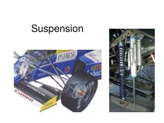
Suspension D.J. Conroy
Last year • Designed with existing frame • Did not use suspension analysis programming • A-arms not easily adjustable • Hard to assemble
This year • Design frame around suspension • Find optimum geometry using Lotus • Make adjustment, machining, and assembly much easier
Geometry • Analyzed using lotus software • Mounting points dictate much of the frame layout
Most Important Aspects • Camber • Castor • Toe • Roll center height
Optimum Settings • -1° camber (static) • 1° change per inch bump/droop • Front toe • -1° toe in static (positive with lotus sign convention) • Minimal change in bump/droop • 5° of castor • Minimal change in bump/droop • Roll center height of about 2 in • Stay positive through bump/droop • Converging A-arms
Pentagon Specs: • Roll Center: • Static: 0.8in • 1 in bump: -1in • 1in droop: 0.7in • Camber: • Static: -1° • 1 in bump: -2.05° • 1in droop: -0.25° • Toe: • Static: 1° • 1 in bump: -12° • 1in droop: 14.5° • 1° roll: 6.5°
Octagon Specs: • Roll Center: • Static: 2.7in • 1 in bump: 1in • 1in droop: 4in • Camber: • Static: -1° • 1 in bump: -2.2° • 1in droop: .1° • Toe: • Static: 1° • 1 in bump: -5° • 1in droop: 7° • 1° roll: + 2.5°
Octagon vs. Pentagon • Advantages: • Lower and shorter (from bottom to top of frame) • Lower COG • Don’t need to worry about a raised front end • Better mounting of steering rack • Much less bump steer • Disadvantages: • Heavier • More frame members
My opinion: • The couple extra frame members and 5 lbs max additional un-sprung weight is worth it to have a much lower center of gravity and much less bump steer.
A arm Dimensions • Upper: • Forward arm 15.08in • Trailing arm 14.70in • Difference: .38in • Angle: 51.7° • Lower: • Forward arm: 15.73in • Trailing arm: 16.09in • Difference: .36in • Angle: 48.2°
Materials • Steel • Good: • Easy to weld • Cheap • Bad: • Heavy • Carbon Fiber • Good: • Light weight • Bad: • Expensive • Hard to bond to steel
Manufacturing and Assembly • Rod ends with built in spacers • Mill push rod mounts • Use steel or carbon fiber rods • Jig: • Accurate • 3 points • Could use mill table
Adjustability • Exposed outer rod end:
Breaking: • tyre: 217.7 lb • Top arm: 114.3 lb • Bottom arm: 332 lb • Verticle: • tyre: 580.6 lb • Top arm: 290 lb • Bottom arm: 290lb • Lateral: • Tyre: 290.3 lb • Top arm: 152.4 lb • Bottom arm: 442.7 lb