Download
1 / 16
160 likes | 321 Views
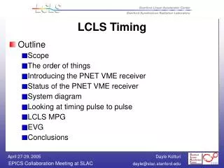
LCLS Timing. Outline Scope SLC Master Pattern Generator Introducing the PNET VME receiver Status of the PNET VME receiver System diagram Timing pulse to pulse LCLS MPG Event Generator and Event Receiver Costs Conclusions. Scope.

E N D
LCLS Timing • Outline • Scope • SLC Master Pattern Generator • Introducing the PNET VME receiver • Status of the PNET VME receiver • System diagram • Timing pulse to pulse • LCLS MPG • Event Generator and Event Receiver • Costs • Conclusions
Scope • LCLS timing system is used to transmit a fiducial 360 Hz signal to all triggered devices in LCLS • System requirements (speed and content) are known: receive 128 bit PNET data at 360 Hz; append add’l info; operate at 120 Hz • The component parts are known: PNET VME receiver, EVG-200 and EVR-200 • The interfaces are being defined
SLC Master Pattern Generator • The one and only SLC Master Pattern Generator (MPG) • Takes as input: 360 Hz fiducial from SLC PDU is the signal to create a new PNET buffer • Performs tasks: • creates PNET buffers • responds to faults • Outputs PNET buffers to all micros and PNET VME receiveron the next 1/360 s fiducial
Status of the VME PNET receiver • Hardware prototype is finished (1 instance) • Board is 3 slots wide to accommodate on board cable modem interface to PNET • Engineering Design Specification doc written • Driver and device support (bi, mbbiDirect to access each variable in PNETbuffer) written. Compiled only for Synergy PPC running RTEMS 4.6.2
LCLS MPG • Takes the PNETbuffer with appended epicsTimeStamp and checksum fault indicators • Adds on LCLS application commands • Adds on any newly detected faults • Writes modified buffer into EVG’s memory, setting flag when done
Event Generator (EVG) • On board FPGA packages/chunks 24 byte LCLS MPG data and sends 2 byte packets to EVR at 125 MHz • Data arrives in EVR in 0.6 microseconds + fiber travel time (which depends on distance) • Driver and device support exists (for sending smaller-sized packets). Conversion to RTEMS (from VxWorks) in progress
Event Receiver (EVR) • Resides in SLC-aware IOC • Receives EventBuffer (EB) from EVG • Contents of EB determine actions taken by SLC-aware IOC during current beam pulse • Driver and device support exists (for receiving smaller-sized packets). Conversion to RTEMS (from VxWorks) needed
Costs • Event Generator EVG-200: 5687 € • Need one (only) in operation and 2 for testing and spare • Event Receiver EVR-200: 2932 € • Need one per chassis where triggers required • Transition Modules: • EVR-OTB-200 (14 triggers): 829 € • EVR-NTB-200 (32 triggers): 1434 €
Conclusions • Progress made with PNET VME receiver • LCLS MPG needs to be designed and implemented • EVR/SLC-aware IOC interface needs defining • Performance and reliability from PNET through to EVG must be measured