Download
1 / 25
250 likes | 253 Views
MuCool is a collaborative research program focused on designing, prototyping, and testing cooling channel components for the MICE experiment. It includes RF development, LH2 absorber research, and high-intensity beam testing at the MuCool Test Area.

E N D
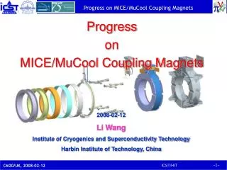
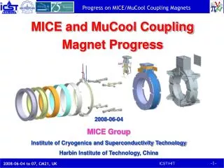
MuCool Overview Muon Cooling R&D
Outline • MuCool Overview AB • Collaboration • MuCool Test Area • Program Synopsis • MTA RF Program A. Moretti • MTA RF Program II D. Huang • RF Modeling J. Norem • LH2 Absorber Status M. A. Cummings
MuCool • Consists of 9 institutions from the US and Japan • Mission • Design, prototype and test all cooling channel components • 201 MHz RF Cavities, LH2 absorbers, SC solenoids • Support MICE (cooling demonstration experiment) • Perform high beam-power engineering test of cooling section components RF Development ANL Fermilab IIT JLAB LBNL Mississippi Absorber R&D Fermilab IIT KEK NIU Mississippi Osaka Solenoids LBNL Mississippi
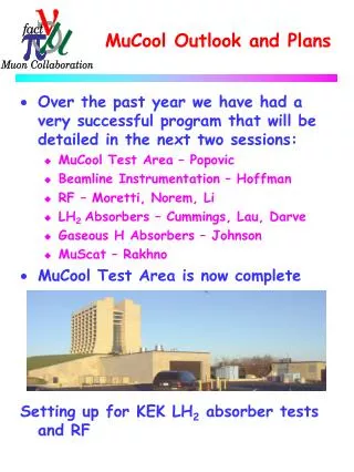
MuCool Test Area • Facility to test all components of cooling channel (not a test of ionization cooling) • At high beam power • Designed to accommodate full Linac Beam • 1.6 X 10¹³p/pulse @15 Hz • 2.4 X 10¹⁴ p/s • » 600 W into 35 cm LH2 absorber @ 400 MeV • RF power from Linac (201 and 805 MHz test stands) • Waveguides pipe power to MTA
MTA • The MTA is the focus of our Activities • RF testing (805 and 201 MHz) • High pressure H2 gas-filled RF • LH2 Absorber tests • High Intensity Beam • Will start with low intensity
MTA Cryo-Infrastructure • We are making good progress with completion of the cryo-plant and transfer-line system. • Our goal is too install/commission the system this FY (well our goal was to install last FY) • Before the shutdown (June) in we can start by April • After the shutdown otherwise • Our current operating costs (LHe) for the MTA magnet are $3-5k/week • We do not have collaboration funds to support this, but • Fermilab will provide $100k of support for MTA operations • Will allow us to run the magnet off LHe dewars for the remainder of FY07 if required
Compressor Room Storage Area Refrigerator Room GHe, LN2 Storage Heat Exch.
Transfer Line System Refrig Room Valve Can Valve Box Can Xfer Line Valve Box Piping
MTA Hall Instrumentation Chipmunk Plastic Scintillator 805 CsI 201 Magnet
MTA Beam Line • 400 MeV beamline for the MTA has been designed • Under Craig Moore/Carol Johnstone • External Beams Department • Developed Engineering Design • Cost • Schedule • Safety Analysis • Linac Area and Beamline • Shielding Assessment for MTA • First Phase will be low-intensity • Negotiating with lab for $250k to install this year MTA
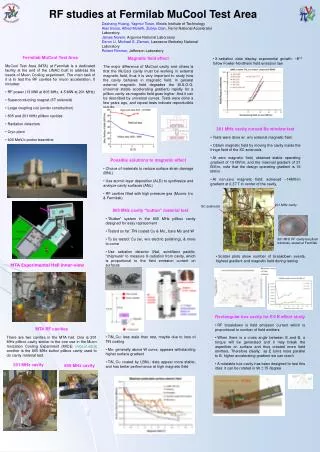
RF Cavity R and D ANL/FNAL/IIT/LBNL/UMiss
Fundamental Focus Of RF R&D • Study the limits on Accelerating Gradient in NCRF cavities in magnetic field • However • We believe that the behavior of RF systems in general can be accurately described (predicted) by • Tensile strength of the material(s) used in the cavity fabrication (T) • Local surface field enhancements (beq) Esurf = £ Ö(2T/eo)/beq • This applies to all accelerating structures • In SC structures local heating becomes problem first • Follows universal curve
805 MHz • Data seem to follow universal curve • Max stable gradient degrades quickly with B field • Remeasured • Same results • Does not condition Gradient in MV/m Peak Magnetic Field in T at the Window
Next 805 MHz study - Buttons • Button test • Evaluate various materials and coatings • Quick Change over
RF R&D – 201 MHz Cavity Design • The 201 MHz Cavity is now operating • New data on x-ray backgrounds will be presented
201 Simulations • Simulation work from our colleagues at Cockcroft Institute • Single coupler @ 2.5MW input
High Pressure H2 Filled Cavity WorkMuon’s Inc • High Pressure Test Cell • Study breakdown properties of materials in H2 • Run in B field • No degradation in M.S.G. up to » 3.5T
Absorber R and D IIT/KEK/NIU/Osaka/UMiss
Absorber Design Issues • 2D Transverse Cooling and • Figure of merit: M=LRdEm/ds M2 (4D cooling) for different absorbers H2 is clearly Best - Neglecting Engineering Issues Windows, Safety
Convective Absorber Activities • KEK Convector Absorber upgrades • Electrical Heater • New Temperature sensors • LH liquid level sensor • Have now been installed and system has been tested • Ready for LH2 run • After safety approval Absorber Body being modified in Lab 6 at Fermilab
MuCool Plans for the Coming Year • 805 MHz RF studies – Buttons (with and without B field) • Materials tests • Surface treatment • Use information from LEAP studies (surface studies) • Local Electrode Atom Probe • 201 MHz RF • Conditioning in B field • Install Curved Be Windows and repeat • Second round of tests with KEK convective absorber • Window of opportunity is until C.I. installation starts • Complete MTA cryo infrastructure installation and commission system • Begin Installation of beam line components