Download

1 / 31
320 likes | 442 Views
WAN Design Serial Line Protocols. WAN Design Requirements. Understanding the Customer Requirement

E N D
WAN Design Requirements • Understanding the Customer Requirement • How does one progress from conception to reality in designing their network? This is as difficult to find a single best answer for as if one were to try determining the best earth-bound route to go from Bannock to Frankfurt. No single right answer would be given. But knowing this should not keep you from gathering enough information to make intelligent choices and concessions. • In all cases the reader must remember to work toward a wide area network that is as fast as possible, within any understood constraints, that handles the data accurately and securely, for a reasonable cost. To accomplish this we need to ask some basic questions. Below are some suggested questions to help you get started: • • Is this a new installation or replacing an existing? • • If existing, what problems does the customer currently face that they would like corrected? • • What are the requirements? • • What is the rate of data transfer? • • Must the network be high speed in both directions or only one?
WAN Design Requirements Cont. • By answering some of these we might determine performance and reliability requirements. Other questions would be: • • What levels of security need to be in place? • • If this customer wants these routers hooked to the Internet then they need to have designed for the stateful firewall and access policies to be in place. • • What would be the areas we could compromise? • • Is high performance is priority at all locations or only at some. • • Are there areas that are not “top priority?” • Other questions would be: • • Is this for data only or is this a combined data and voice solution? • • Is the voice solution traditional TDM voice or Voice over IP? • • Does the customer need a strategy for redundancy? • • If yes then consider, through risk assessment, what should be redundant the WAN links, the carrier or ISP, the routers themselves, the modules in the routers? • • How much monthly cost do I tolerate for one day of downtime? • • Then what would be the best possible network design? • • In order to answer this question the previous questions need to be addressed and then combined with what is available in the locations of the customer locations. Your best possible design will be a combination of requirements aligned with the technologies and services available to accomplish them. • These are just a few of the questions one would need to answer before designing the network.
WAN Design Requirements Cont. • Application availability: • Networks carry application information between computers. • If the applications are not available, the network is not doing its job. • Total cost of ownership: • Information Systems (IS) department budgets often run in the millions of dollars. • More businesses rely on electronic data, therefore the costs of computing resources will continue to rise.
WAN Design Requirements Cont. • Network designs tend to follow one of two general design strategies: • Mesh: • The network topology is flat. • All routers perform essentially the same functions, and there is usually no clear definition of where specific functions are performed. • Expansion of the network tends to proceed in a haphazard, arbitrary manner. • Hierarchical: • The structure the network is organized in layers, each of which has one or more specific functions. • Data traffic flows based on source / destination addressing.
WAN Design Requirements Cont. • Benefits to using a hierarchical model include the following: • Easier to implement. • Easier to manage. • Easier to troubleshoot. • Improved scalability. • Predictability. • Protocol support.
The Three Hierarchical WAN Design Layers • A hierarchical network design includes the following three layers: • The CORE layer: • Provides optimal transport between sites. • The DISTRIBUTION layer: • Provides policy-based connectivity. • The ACCESS layer: • Provides workgroup and user access to the network. • Could also be called the 3 levels of a router hierarchy.
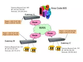
Core Layer • Provides fast WAN area connections between remote sites, tying a campus networks together in a corporate or enterprise WAN. • Is usually implemented as a WAN. • Needs redundant paths. • Can withstand individual circuit outages and continue to function. • Links are point-to-point. • There are rarely any hosts in the core layer. • Should not perform any filtering – slows down performance. • Core services (for example, T1/T3, Frame Relay, SMDS) typically are leased from a telecom service provider.
Distribution Layer • Provides network services to multiple LANs within a WAN environment. • This is where the WAN backbone network is found, and it is typically based on Fast Ethernet. • This is implemented on large sites and is used to interconnect buildings. • Provides boundary definition, and it is the layer at which packet manipulation occurs. • Can be summarized as the layer that provides policy-based connectivity.
Access Layer • The access layer is usually a LAN or a group of LANs, typically Ethernet or Token Ring, that provide users with frontline access to network services. • Almost all hosts are attached to the network, including servers of all kinds and user workstations. • Allows logical segmentation of the network and grouping of users based on their function. • Can also use access control lists or filters to further optimize the needs of a particular set of users. • Workgroup servers should be located here. • The main goal of the Access layer is to isolate the broadcast traffic between the individual workgroups, segments, or LANs.
Access Layer Cont. • In the campus environment, access-layer functions can include the following: • Shared bandwidth. • Switched bandwidth. • MAC-layer filtering. • Microsegmentation. • The access layer connects users into LANs, and LANs into WAN backbones or WAN links.
Other Designs • A three-layer model can meet the needs of most enterprise networks. • However, a two-layer design may be adequate or even a single layer flat network. • A hierarchical structure should still be planned or maintained to allow these network designs to expand to three layers as the need arises.
One Layer Design • In a 1 layer design, the key design decision becomes the placement of servers: • They can be distributed across multiple LANs • Or concentrated in a central server farm location. • A one-layer design is typically implemented if there are only a few remote locations in the company, and access to applications is mainly done via the local LAN to the site file server. • Each site is its own broadcast domain.
Two Layer Design • In a two-layer design, a WAN link is used to interconnect separate sites. • Inside the site, multiple LANs may be implemented, with each LAN segment being its own broadcast domain.
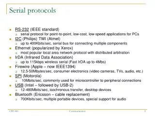
Serial Line Protocols • PPP (Point to Point Protocol) • Point-to-Point Protocol (PPP) is the name of a single protocol, but most often “PPP” refers to the entire suite of protocols that are related to PPP. PPP is a layered protocol, starting with a Link Control Protocol (LCP) for link establishment, configuration and testing. Once the LCP is initialized, one or many of several Network Control Protocols (NCPs) can be used to transport traffic for a particular protocol suite. The IP Control Protocol (IPCP), documented in RFC 1332, permits the transport of IP packets over a PPP link. • PPP differs from HDLC primarily in that you can use some basic security methods with it. You can configure WAN routers (or other devices) to use optional protocols in the PPP suite. In addition, many protocols in the PPP suite, such as LCP, allow you to manually configure options. • When one of the peers in a PPP session has been configured to use protocols or options that are not used by default, the peers negotiate these options. They do so by exchanging configuration frames for the protocol in question.
PPP • Summary of Major Points • • Point-to-Point. One point to a single other point. • • Some security available through authentication. • How This Technology is Used • • Site to site, point to point, transport of upper layer protocol, over a leased physical link. • • To establish an authenticated connection from router to ISP router over the physical connection when often this connection is ATM over ADSL, or Ethernet through an ADSL modem. • What to Determine During Planning • • The authentication method desired, typically CHAP or PAP. • • The passwords used during authentication.
PPP • Advantages • PPP allows for a wide range of features one of which is authentication of the other network device attempting to connect. This particular feature makes it extremely suitable for ADSL and Internet connectivity. • Disadvantages • There is no capability in HDLC or PPP to cross carrier boundaries. There is no network-to-network interface. • What to Determine During Planning • • The PPP attributes for the router at the other end of the connection. • • Determine if passwords and authentication methods are required (typically these are not needed in a private physical network).
Password Authentication Protocol • PAP is a very straight-forward authentication scheme, consisting of only two basic steps, as shown in the image on the next slide. • Authentication Request: The initiating device sends an Authenticate-Request message that contains a name and a password. • Authentication Reply: The responding device looks at the name and password and decides whether to accept the initiating device and continue in setting up the link. If so, it sends back an Authenticate-Ack. Otherwise, it sends an Authenticate-Nak.
PAP PAP works using a simple exchange of a request containing name and password information, and a reply indicating whether or not authentication was successful.
Challenge Handshake Authentication Protocol • Challenge Handshake Authentication Protocol (CHAP) • The most important difference between PAP and CHAP is that CHAP doesn't transmit the password across the link. Now you may be wondering—if that's the case, how is the password verified? Well, think of it this way. PAP works by the initiator telling the authenticator “here's the password I know, see if it matches yours”. CHAP does this by having each of the devices use the password to perform a cryptographic computation and then check if they each get the same result. If they do, they know they have the same password.
CHAP • CHAP Authentication Procedure • In CHAP, a basic LCP link is set up between the initiator (calling client) and authenticator (generally the server that is deciding whether to grant authentication). The authenticator then takes charge of the authentication process, using a technique called a three-way handshake. This is a fairly common general authentication procedure; the same basic technique is used, for example, in IEEE 802.11 Shared Key Authentication. • The three-way handshake steps are as follows: • Challenge: The authenticator generates a frame called a Challenge and sends it to the initiator. This frame contains a simple text message (sometimes called the challenge text). The message has no inherent special meaning so it doesn't matter if anyone intercepts it. The important thing is that after receipt of the Challenge both devices have the same challenge message. • Response: The initiator uses its password (or some other shared “secret” that the authenticators also knows) to encrypt the challenge text. It then sends the encrypted challenge text as a Response back to the authenticator. • Success or Failure: The authenticator performs the same encryption on the challenge text that the initiator did. If the authenticator gets the same result that the initiator sent it in the Response, the authenticator knows that the initiator had the right password when it did its encryption, so the authenticator sends back a Success message. Otherwise, it sends a Failure message.
CHAP uses a three-way handshake beginning with a Challenge from the authenticating device (usually the remote server accessed by a host). This message is encrypted and returned to the authenticating device, which checks to see if the device trying to authenticate used the correct password (or other “shared secret”).
Benefits of CHAP • You can see the beauty of this: it verifies that the two devices have the same “shared secret” but doesn't require that the secret be sent over the link. The Response is calculated based on the password, but the content of the Response is encrypted and thus, much harder to derive the password from. CHAP also provides protection against replay attacks, where an unauthorized user captures a message and tries to send it again later on. This is done by changing an identifier in each message and varying the challenge text. Also, in CHAP the server controls the authentication process, not the client that is initiating the link.
Note: • Configuring PPP, PAP and CHAP will be shown by the Cisco hand out documents.
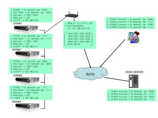
Practical • Tonight we will cover much of the same that we have been. We will be setting up a wireless network. The following is to be done: • Setup Server 2003 with Active Directory and DNS. • Setup Router to act as DHCP. • Connect a Wireless Access Point to the Router. • Connect the Server 2003 computer to the Router. • Setup a Wireless USB Dongle on a Windows XP machine that connects to the wireless network you setup on the Wireless Access Point. • Connect the Windows XP computer to the domain and login wirelessly.