Download
1 / 61
671 likes | 938 Views
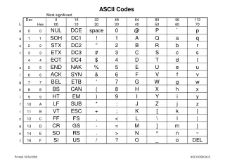
Digital Communication Systems Lecture 5, Prof. Dr. Habibullah Jamal. Under Graduate, Spring 2008. Chapter 4: Bandpass Modulation and Demodulation. Bandpass Modulation is the process by which some characteristics of a sinusoidal waveform is varied according to the message signal.

E N D
Digital Communication SystemsLecture 5, Prof. Dr. Habibullah Jamal Under Graduate, Spring 2008
Chapter 4: Bandpass Modulation and Demodulation • Bandpass Modulation is the process by which some characteristics of a sinusoidal waveform is varied according to the message signal. • Modulation shifts the spectrum of a baseband signal to some high frequency. • Demodulator/Decoder baseband waveform recovery
4.1 Why Modulate? • Most channels require that the baseband signal be shifted to a higher frequency • For example in case of a wireless channel antenna size is inversely proportional to the center frequency, this is difficult to realize for baseband signals. • For speech signal f = 3 kHz =c/f=(3x108)/(3x103) • Antenna size without modulation /4=105 /4 meters = 15 miles - practically unrealizable • Same speech signal if amplitude modulated using fc=900MHz will require an antenna size of about 8cm. • This is evident that efficient antenna of realistic physical size is needed for radio communication system • Modulation also required if channel has to be shared by several transmitters (Frequency division multiplexing).
4.2 Digital Bandpass Modulation Techniques Three ways of representing bandpass signal: • (1) Magnitude and Phase (M & P) • Any bandpass signal can be represented as: • A(t) ≥ 0 is real valued signal representing the magnitude • Θ(t) is the genarlized angle • φ(t) is the phase • The representation is easy to interpret physically, but often is not mathematically convenient • In this form, the modulated signal can represent information through changing three parameters of the signal namely: • Amplitude A(t) : as in Amplitude Shift Keying (ASK) • Phase φ(t) : as in Phase Shift Keying (PSK) • Frequency dΘ(t)/ dt : as in Frequency Shift Keying (FSK)
Angle Modulation • Consider a signal with constant frequency: • Its instantaneous frequency can be written as: or
Phase Shift Keying (PSK) or PM • Consider a message signal m(t), we can write the phase modulated signal as
Frequency Shift Keying (FSK) or FM • In case of Frequency Modulation where:
4.2.1 Phasor Representation of Sinusoid • Consider the trigonometric identity called the Euler’s theorem: • Using this identity we can have the phasor representation of the sinusoids. Figure 4.2 below shows such relation:
Phasor Representation of Amplitude Modulation • Consider the AM signal in phasor form:
Phasor Representation of FM • Consider the FM signal in phasor form:
Basic Digital Modulation Schemes: Amplitude Shift Keying (ASK) Frequency Shift Keying (FSK) Phase Shift Keying (PSK) Amplitude Phase Keying (APK) For Binary signals (M = 2), we have Binary Amplitude Shift Keying (BASK) Binary Phase Shift Keying (BPSK) Binary Frequency Shift Keying (BFSK) For M > 2, many variations of the above techniques exit usually classified as M-ary Modulation/detection Digital Modulation Schemes
Figure4.5: digital modulations, (a) PSK (b) FSK (c) ASK (d) ASK/PSK (APK)
Amplitude Shift Keying • Modulation Process • In Amplitude Shift Keying (ASK), the amplitude of the carrier is switched between two (or more) levels according to the digital data • For BASK (also called ON-OFF Keying (OOK)), one and zero are represented by two amplitude levels A1and A0
Analytical Expression: where Ai = peak amplitude Hence, where
Where for binary ASK (also known as ON OFF Keying (OOK)) • Mathematical ASK Signal Representation • The complex envelope of an ASK signal is: • The magnitude and phase of an ASK signal are: • The in-phase and quadrature components are: the quadrature component is wasted.
It can be seen that the bandwidth of ASK modulated is twice that occupied by the source baseband stream • Bandwidth of ASK • Bandwidth of ASK can be found from its power spectral density • The bandwidth of an ASK signal is twice that of the unipolar NRZ line code used to create it., i.e., • This is the null-to-null bandwidth of ASK
If raised cosine rolloff pulse shaping is used, then the bandwidth is: • Spectral efficiency of ASK is half that of a baseband unipolar NRZ line code • This is because the quadrature component is wasted • 95% energy bandwidth
Detectors for ASKCoherent Receiver • Coherent detection requires the phase information • A coherent detector mixes the incoming signal with a locally generated carrier reference • Multiplying the received signal r(t) by the receiver local oscillator (say Accos(wct)) yields a signal with a baseband component plus a component at 2fc • Passing this signal through a low pass filter eliminates the high frequency component • In practice an integrator is used as the LPF
The output of the LPF is sampled once per bit period • This sample z(T) is applied to a decision rule • z(T) is called the decision statistic • Matched filter receiver of OOK signal • A MF pair such as the root raised cosine filter can thus be used to shape the source and received baseband symbols • In fact this is a very common approach in signal detection in most bandpass data modems
Noncoherent Receiver • Does not require a phase reference at the receiver • If we do not know the phase and frequency of the carrier, we can use a noncoherent receiver to recover ASK signal • Envelope Detector: • The simplest implementation of an envelope detector comprises a diode rectifier and smoothing filter
Frequency Shift Keying (FSK) • In FSK, the instantaneous carrier frequency is switched between 2 or more levels according to the baseband digital data • data bits select a carrier at one of two frequencies • the data is encoded in the frequency • Until recently, FSK has been the most widely used form of digital modulation;Why? • Simple both to generate and detect • Insensitive to amplitude fluctuations in the channel • FSK conveys the data using distinct carrier frequencies to represent symbol states • An important property of FSK is that the amplitude of the modulated wave is constant • Waveform
Analytical Expression • General expression is Where
Binary FSK • In BFSK, 2 different frequencies, f1 and f2 = f1 + ∆f are used to transmit binary information • Data is encoded in the frequencies • That is, m(t) is used to select between 2 frequencies: • f1 is the mark frequency, and f2 is the space frequency
Binary Orthogonal Phase FSK • When w0 an w1 are chosen so that f1(t) and f2(t) are orthogonal, i.e., • form a set of K = 2 basis orthonormal basis functions
Phase Shift Keying (PSK) • General expression is • Where
3. Coherent Detection of Binary FSK • Coherent detection of Binary FSK is similar to that for ASK but in this case there are 2 detectors tuned to the 2 carrier frequencies • Recovery of fc in receiver is made simple if the frequency spacing between symbols is made equal to the symbol rate.
Non-coherent Detection • One of the simplest ways of detecting binary FSK is to pass the signal through 2 BPF tuned to the 2 signaling freqs and detect which has the larger output averaged over a symbol period
Phase Shift Keying (PSK) • In PSK, the phase of the carrier signal is switched between 2 (for BPSK) or more (for MPSK) in response to the baseband digital data • With PSK the information is contained in the instantaneous phase of the modulated carrier • Usually this phase is imposed and measured with respect to a fixed carrier of known phase – Coherent PSK • For binary PSK, phase states of 0o and 180o are used • Waveform:
Analytical expression can be written as where • g(t) is signal pulse shape • A = amplitude of the signal • ø = carrier phase • The range of the carrier phase can be determined using • For a rectangular pulse, we obtain
We can now write the analytical expression as • In PSK the carrier phase changes abruptly at the beginning of each signal interval while the amplitude remains constant carrier phase changes abruptly at the beginning of each signal interval Constant envelope
We can also write a PSK signal as: • Furthermore, s1(t) may be represented as a linear combination of two orthogonal functions ψ1(t) and ψ2(t) as follows Where
Using the concept of the orthogonal basis function, we can represent PSK signals as a two dimensional vector • For M-ary phase modulation M = 2k, where k is the number of information bits per transmitted symbol • In an M-ary system, one of M ≥ 2 possible symbols, s1(t), …, sm(t), is transmitted during each Ts-second signaling interval • The mapping or assignment of k information bits into M = 2kpossible phases may be performed in many ways, e.g. for M = 4
A preferred assignment is to use “Gray code” in which adjacent phases differ by only one binary digit such that only a single bit error occurs in a k-bit sequence. Will talk about this in detail in the next few slides. • It is also possible to transmit data encoded as the phase change (phase difference) between consecutive symbols • This technique is known as Differential PSK (DPSK) • There is no non-coherent detection equivalent for PSK except for DPSK
M-ary PSK • In MPSK, the phase of the carrier takes on one of M possible values • Thus, MPSK waveform is expressed as • Each si(t) may be expanded in terms of two basis function Ψ1(t) and Ψ2(t) defined as
Quadrature PSK (QPSK) • Two BPSK in phase quadrature • QPSK (or 4PSK) is a modulation technique that transmits 2-bit of information using 4 states of phases • For example • General expression: Each symbol corresponds to two bits
One of 4 possible waveforms is transmitted during each signaling interval Ts • i.e., 2 bits are transmitted per modulation symbol → Ts=2Tb) • In QPSK, both the in-phase and quadrature components are used • The I and Q channels are aligned and phase transition occur once every Ts = 2Tbseconds with a maximum transition of 180 degrees • From • As shown earlier we can use trigonometric identities to show that
In terms of basis functions we can write sQPSK(t) as • With this expression, the constellation diagram can easily be drawn • For example:
Coherent Detection1. Coherent Detection of PSK • Coherent detection requires the phase information • A coherent detector operates by mixing the incoming data signal with a locally generated carrier reference and selecting the difference component from the mixer output • Multiplying r(t) by the receiver LO (say A cos(ωct)) yields a signal with a baseband component plus a component at 2fc • The LPF eliminates the high frequency component • The output of the LPF is sampled once per bit period • The sampled value z(T) is applied to a decision rule • z(T) is called the decision statistic
Matched filter receiver • A MF pair such as the root raised cosine filter can thus be used to shape the source and received baseband symbols • In fact this is a very common approach in signal detection in most bandpass data modems
2. Coherent Detection of MPSK • QPSK receiver is composed of 2 BPSK receivers • one that locks on to the sine carrier and • the other that locks onto the cosine carrier
If • Decision: 1. Calculate zi(t) as 2. Find the quadrant of (Z0, Z1)
A coherent QPSK receiver requires accurate carrier recovery using a 4th power process, to restore the 90o phase states to modulo 2π
4.3 Detection of Signals in Gaussian Noise • Detection models at baseband and passband are identical • Equivalence theorem (for linear systems): • Linear signal processing on passband signal and eventual heterodyning to baseband is equivalent to first heterodyning passband signal to baseband followed by linear signal processing • Where Heterodyning = Process resulting in spectral shift in signal e.g. mixing • Performance Analysis and description of communication systems is usually done at baseband for simplicity
4.4 Coherent Detection 4.4.1 Coherent Detection of PSK • Consider the following binary PSK example n(t) = zero-mean Gaussian random process • Where φ : phase term is an arbitrary constant E: signal energy per symbol T: Symbol duration • Single basis function for this antipodal case:
Transmitted signals si(t) in terms of ψ1(t) and coefficients ai1(t) are • Assume that s1 was transmitted, then values of product integrators with reference to ψ1 are
where E{n(t)}=0 • Decision stage determines the the location of the transmitted signal within the signal space • For antipodal case choice of ψ1(t) = √2/T cosw0t normalizes E{zi(T)} to ±√E • Prototype signals si(t) are the same as reference signals ψj(t) except for normalizing scale factor • Decision stage chooses signal with largest value of zi(T)