Download
1 / 8
80 likes | 206 Views
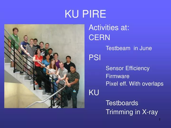
KU PIRE. Activities at: CERN Testbeam in June PSI Sensor Efficiency Firmware Pixel eff. With overlaps KU Testboards Trimming in X-ray. CERN - testbeam. When: June 2-18 Goal: Measure the efficiency and spatial resolution of present sensors as function of irradiation dose

E N D
KU PIRE Activities at: CERN Testbeam in June PSI Sensor Efficiency Firmware Pixel eff. With overlaps KU Testboards Trimming in X-ray
CERN - testbeam • When: June 2-18 • Goal: Measure the efficiency and spatial resolution of present sensors as function of irradiation dose • What: Pixel telescope • Trigger, 4 chips to define track • Device under test in coldbox • 3T Magnetic field possible • Devices tested: • Unirradiated • 6E14 Neq/cm2 (2years in first layer) • 1.2E15 Neq/cm2 (4 yrs) • 3E15 Neq/cm2 Beam trig t1 t2 dev t3 t4
PSI – Sensor Efficiency • Jennifer and Meghan (with Joaquin) • Goals: • for each run, find when there is a track as defined by the telescope and then see whether there is a hit where expected in the device under test -> efficiency • Measure the spatial resolution and Lorentz angle at different incoming angles • What is happening now: • -Use correlations between pixel hits on different telescope to define track • Resolution from fits shows that the beam is less than one pixel wide • - Loop through hits in first element and project to next one and see whether there is a hit where it is expected. Then a quick alignment will be done.
PSI – Firmware - Yasen • General testboard diagnosing • Internal Timing Calibration • The plan: create algorithm that increments “slope” variable until the two points meet smoothly and precisely independent of hardware • TBM emulator improvements
Internal Timing Calibration • Clock limitations to units of 12.5 ns • Logic cells used for even smaller units of ~0.5-1.5 ns • Logic cell does not change signal, just slightly delays it • Began measuring the timing delay adjustments for values between the 12.5 ns scale using logic cells • KU-11 • KU-23 • PSI-14 Roc attached • PSI board seemed already calibrated (manually), KU boards not 9/21/2014 Yasen Ivanov, KU 5
PSI – pixel overlap efficiency • Valeria started and now helping Cameron (UNL) • Where modules overlap, can measure how efficient the pixel detectors are with data from LHC
KU – Board testing • Will, Avery, Chris, Danny, Thomas • Testboard production/testing • Gatekeeper board production/testing • 10 made, but shipping problems and need to be tested
KU - Trimming • Thomas • What is trimming • For each of 4160 pixels on one Readout Chip (ROC), you need to set the threshold above which the pixel will be read out • There are several bits that need to be set. Current procedure uses a calibration pulse from the ROC itself. Pixels set one at a time and X-talk and other effects not accounted for. • Use X-ray box instead? • This way, real signals are being obtained from the sensors through the readout chain as they are in the detector instead of through just the ROC • Will see if the trimming can be set by looking at the noise