Download
1 / 32
320 likes | 507 Views
CMPE 255: Advanced Computer Communication LECTURE 2:. Medium Access Control Protocols forAd Hoc Networks. RTS. RTS. CTS. CTS. S to R. R to S. S. S. S. RTS. CTS. time. RTS. H to R. noise is heard. FAMA: Floor Acquisition Multiple Access.

E N D
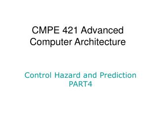
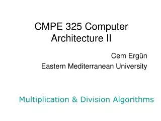
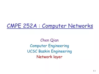
CMPE 255: Advanced Computer CommunicationLECTURE 2: Medium Access Control Protocols forAd Hoc Networks UCSC cmpe255
RTS RTS CTS CTS S to R R to S S S S RTS CTS time RTS H to R noise is heard FAMA: Floor Acquisition Multiple Access • Stations use carrier sensing to send any packet. • The CTS lasts much longer than an RTS to force the interfering sources to detect carrier (from the receiver) and back off. RTS from S arrives at R with no collisions. RTS from H must start within one prop. delay from CTS from R to S. H must hear noise from CTS and backs off! UCSC cmpe255
Packet ready Floor Taken? yes no send RTS delay packet transmission k times wait for a round-trip time CTS back? compute random backoff integer k send packet no yes Basic FAMA Protocol Non-persistent strategy. Same basic algorithm for all CSMA/CA schemes UCSC cmpe255
A packet is successful with probability For we can approximate: Throughput of FAMA Two mutually exclusive events: packet is successful or a collision occurs. Therefore: The utilization period is only that portion of a packet transmission that has no overhead, that is: Notice the impact of the RTS-CTS overhead! Substituting: UCSC cmpe255
Throughput of FAMA • FAMA (and all collision-avoidance protocols) is always below CSMA/CD. UCSC cmpe255
RIMA-DP timing diagrams Waiting period X RTR DATA Node X sends an RTR and after seconds receives a DATA packet and then sends its DATA DATA Z Waiting period RTR DATA X Node X sends an RTR and node Z replies with a CTS; node X sends its DATA Z CTS X RTR Nodes X and Z send RTRs within seconds and therefore a collision occurs Z RTR channel collision BACKOFF Noise detected at Z X RTR NTR BACKOFF Due to interference from node Z, node X sends an NTR to stop the handshake Z interference UCSC cmpe255
Throughput of RIMA-DP • The probability of success is the probability that an RTR is sent in the clear, because any RTR produces one or two data packets, i.e., • The probability with which the polled node has data is • The probability with which the poled node has no data is • The length of an average busy period always includes an RTR, a prop delay, and the average time between the first and the last RTR of the busy period; therefore, UCSC cmpe255
first packet starts (A) last interfering packet starts (B) NEW NEW A RTR B time successful packet: idle period: collision interval: Throughput of RIMA-DP NEW DATA CTS • The length of the average idle period is simply 1/lambda • The average utilization period is idle period UCSC cmpe255
Throughput of RIMA-DP • The throughput is simple the length of the ave. utilization period divided by the length of the average cycle: UCSC cmpe255
Throughput Analysis • 500 Byte data packets; 1Mbps network speed; maximum distance between nodes is 1 mile; on the left a 10 node network; on the right a 50 node network UCSC cmpe255
Limitations of Colision Avoidance • Collision avoidance is meant for unicast packets. • A large number of network-level control and data packets are multicast and broadcast in nature. UCSC cmpe255
Collision-Avoidance Transmission Scheduling (CATS) • A contention and reservation based topology-dependent multi-channel scheduling protocol. • Schedules unicasting, multicasting and broadcasting traffics simultaneously. • Data packets are sent collision-free in the presence of hidden terminals. • Supports real-time applications and node mobility. • Provides better spatial reuse than topology-independent scheduling since frame length depends only on node degree. • Works well with commercial SFH radios in ISM bands. UCSC cmpe255
Time and Channel Organization • Time is slotted and slots are grouped into frames. A slot is further divided into six mini-slots. • Multiple channels are available: one signaling channel (SCH), one broadcast data channel (BCH) and a number of other data channels (DCHs). • A data link refers to a particular DCH or the BCH in a particular slot. • Small control packets called beacons are used to contend for and reserve data links. UCSC cmpe255
Identifying Reservations and Data Transmission Frame slot 1 slot 2 slot 3 slot L LRB Unicast Data Packet Unicast LRB LRB LRB Multicast Data Packet Multicast LRB Broadcast Data Packet Broadcast MS1 MS2 MS3 MS4 MS5 MS6 Signaling CH Broadcast CH Reserved Data CH's LRB: Link Reservation Beacon UCSC cmpe255
Frame slot 1 slot 2 slot 3 slot 4 slot L Unsuccessful SL SL RUB RL C/N unicast contention Successful SL SL RUB RL CUB UCD unicast contention Unsuccessful SL SL RMB SMB/N multicast contention Successful multicast SL SL RMB Clear MCD contention Unsuccessful SL RBB SBB/N broadcast contention Successful SL RBB Clear BCD broadcast contention MS1 MS2 MS3 MS4 MS5 MS6 Signaling CH Data CH RUB: Request Unicast Beacon, RMB: Request Multicast Beacon, RBB: Request Broadcast Beacon CUB: Concur with Unicast Breacon, SMB: Stop Multicast Beacon, SBB: Stop Broadcast Beacon UCD: UniCast Data, MCD: MultiCast Data, BCD: BroadCast Data, SL: Sender Listens RL: Receiver Listens, C/N: Clear/Noise Making Reservations for Data Transmissions RL SL RL SL SL SL Broadcast CH UCSC cmpe255
Frame Length Worst-case minimum frame length L and number of DCHs C (assuming N > d2, d: the max node degree, and N: the node population in the network): • For broadcast: L = d2 + 1. • For unicast: • L = 2d, C = d, if each node unicasts once in each frame; Or • L = 2(2d -1), C = 2d -1, if each node unicasts to each neighbor once in each frame. UCSC cmpe255
Approximate Unicast Throughput Analysis Results BAMA: d=10, L=20 slots, C=10 DCH's, AFL in slots 1 0.9 0.8 0.7 0.6 Throughput per Node S 0.5 0.4 0.3 0.2 AFL=100 AFL=10 AFL=2 0.1 AFL=1 0 0 0.2 0.4 0.6 0.8 1 1.2 Offered Load per Node G d: node degree L: frame length AFL: average flow (message) length UCSC cmpe255
BAMA: N=16 nodes, L=16 slots, AFL in slots 1 0.9 0.8 0.7 0.6 Throughput per Node S 0.5 0.4 0.3 0.2 AFL=100 AFL=10 AFL=2 0.1 AFL=1 0 0 0.1 0.2 0.3 0.4 0.5 0.6 0.7 0.8 0.9 Offered Load per Node G Approximate Broadcast Throughput Analysis Results N: number of nodes L: frame length AFL: average flow (message) length UCSC cmpe255
Approximate Performance Analysis • Throughput is analyzed for two cases: unicast traffic over a hyper-cube topology and broadcast traffic over a fully-connected topology. • Each node can reserve at most one slot for transmission in each frame with the worst-case minimum frame length and number of data channels. • We consider Poison sources and geometrically distributed variable-length flows (messages). • Throughput is defined as the probability that a node has a reserved link for transmission in a frame. UCSC cmpe255
Likmitations in CATS • Collision avoidance dialogue is needed! • How can we eliminate the CA in CATS? • Goal is to have a topology-dependent transmission schedule! • Protocol needs to implement a distributed election of schedules and such schedules must be transmitted persistently without eating too much bandwidth! UCSC cmpe255
Collision Resolution and Backoff Strategies • Used to stabilize the system by preventing traffic loads that exceed its capacity. • Collision resolution: Let packet that collide resolve when each is transmitted and block new traffic from entering the system. • Backoff strategies: Increase the time between retransmissions when traffic load (that creates collisions) increases. UCSC cmpe255
Nodes 1 to 49 can try again; node 5 succeeds! (must be only node in range) Nodes 5, 50, 70, 80 collide Nodes 76 to 100 must wait; Node 80 waits Nodes 50 to 100 must wait for all collisions from 1 to 49 to be resolved Nodes 50 to 75 can try; 50 and 70 collide Nodes 50 to 62 can try; 50 succeeds (must be only in range) Node 70 waits Nodes 63 to 70 can try; 70 succeeds Nodes 76 to 100 can try; 80 succeeds! Collision Resolution Algorithm • Assume a fully-connected network. • Each node maintains a stack, a HighID, a LowID and knows the maximum ID in the system UCSC cmpe255
Average Delay of MAC Protocols • We want to measure or compute the average time from the instant the first bit of a packet is first transmitted to the moment the last bit is received correctly at the destination. • Assume that arrivals (of new and retransmitted data or control packets) to the channel are Poisson. • Assume fully-connected networks. UCSC cmpe255
The average number of transmissions needed for a packet to be received correctly is Therefore, the number of retransmissions is Average Delay in ALOHA Assumptions: A satellite channel with propagation delay NxP, where P is the packet length and NxP >> P A retransmission is sent after an average backoff time of BxP seconds. Direct method: A packet is transmitted (G/S-1) times in error (due to collisions) and each such transmission wastes P+NxP +BxP seconds. The last transmission is successful and must take P+NxP seconds. Therefore, the average delay incurred is: UCSC cmpe255
START END BACK OFF Average Delay in ALOHA Indirect Method: Based on the fact that the success of a transmission is independent of others, and knowing how many times we have retransmitted does not change the likelihood of success in the next transmission! We use a diagram showing possible states, probabilities of transition, and delay incurred in that transition. From the diagram. we obtain a number of simultaneous equations that we solve to obtain delay from START to END. UCSC cmpe255
From the diagram we have: Substituting we obtain the same result. Average Delay in ALOHA Solving these two equations: The same method can be applied on the other MAC protocols! UCSC cmpe255
Average Delay of ALOHA • The delay increases exponentially with heavy load, which is not acceptable for real-time applications. UCSC cmpe255