Download

1 / 72
730 likes | 944 Views
Occlusion-Aware Multi-View Reconstruction of Articulated Objects for Manipulation. Xiaoxia Huang Committee members Dr. Stanley Birchfield (Advisor) Dr. Ian Walker Dr. John Gowdy Dr. Damon Woodard. Motivation. Service robots. Care-O-bot 3 ( Fraunhofer IPA ). Robot Rose ( TSR ).

E N D
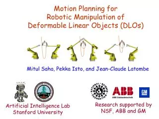
Occlusion-Aware Multi-View Reconstruction ofArticulated Objects for Manipulation Xiaoxia Huang Committee members Dr. Stanley Birchfield (Advisor) Dr. Ian Walker Dr. John Gowdy Dr. Damon Woodard
Motivation Service robots Care-O-bot 3 ( Fraunhofer IPA ) Robot Rose ( TSR )
Motivation Domestic robots in many applications require manipulation of articulated objects • Tools: scissors, shears, pliers, stapler • Furniture: cabinets, drawers, doors, windows, fridge • Devices: laptop, cell phone • Toys: truck, puppet, train, tricycle Important problem: Learning kinematic models
Approach • Part 1: Reconstruct 3D articulated model using multiple perspective views • Part 2: Manipulate articulated objects – even occluded parts • Part 3: Apply RGBD sensor to improve performance
Related Work [ Ross et al., IJCV 2010 ] [ Katz et al., ISER 2010 ] [ Sturm et al., IJCAI 2009, IROS 2010 ] [ Sturm et al., ICRA 2010 ] [ Yan et al., PAMI 2008 ]
Our Approach Recovers kinematic structure from images Features: • Uses single camera • Produces dense 3D models • Recovers both prismatic and revolute joints • Handles multiple joints • Provides occlusion awareness
Approach • Part 1: Reconstruct 3D articulated model using multiple perspective views • Part 2: Manipulate articulated objects – even occluded parts • Part 3: Apply RGBD sensor to improve performance
Procrustes-Lo-RANSAC (PLR) {I1} P 3D reconstruction Alignment / Segmentation {I2} Q t R Axis direction estimation 3D joint estimation 2D joint estimation θ u w Axis point estimation w … {I1} {I2} …
Procrustes-Lo-RANSAC (PLR) Axis direction estimation u w Axis point estimation w … {I1} {I1} P 3D reconstruction Alignment / Segmentation {I2} {I2} Q … t R 3D joint estimation 2D joint estimation θ
Camera Calibration Output K, R, t Camera model intrinsic parameters K object point image point extrinsic parameters Features x’ SIFT {I} Input Bundler: http://phototour.cs.washington.edu/bundler/
SIFT Features • Input images • SIFT features[ Lowe, IJCV 2004 ] • Matched SIFT features 658 keypoints 651 keypoints 24 matches
Camera Calibration Minimize error Structure from motion Output EXIF tag or default value K, R, t Camera model intrinsic parameters K object point image point extrinsic parameters Features x’ SIFT {I} Input Bundler: http://phototour.cs.washington.edu/bundler/
Camera Calibration Camera positions 3D model with 147 images Toy truck
3D Model Reconstruction patch Image projection of a patch Object • Expand to neighboring empty image cells • Not expanded if there is a depth discontinuity I1 I2 PMVS: http://grail.cs.washington.edu/software/pmvs/
3D Model Reconstruction 3D model from Bundler 3D model from PMVS
Procrustes-Lo-RANSAC (PLR) {I1} {I1} P {I2} {I2} Q t R Axis direction estimation u w Axis point estimation w … 3D reconstruction Alignment / Segmentation … 3D joint estimation 2D joint estimation θ
Alignment / Segmentation ASIFT Find closest 3D correspondence S1 Project into image C Match feature S2 Find closest ASIFT update End N Good? R, t,σ Y Segment … F1 {I1} P … Q {I2} Procrustes + Lo-RANSAC F2
Procrustes Analysis {A} {B} Procrustes analysisis the process of performing a shape-preserving similarity transformation. Greek myth http://www.mythweb.com/today/today07.html
Procrustes Algorithm μ μ X Y X X Y Step 1:Translation Y
Procrustes Algorithm Y X X Y Step 2:Scale
Procrustes Algorithm X Y Step 3:Rotation R
Procrustes-Lo-RANSAC (PLR) {I1} {I1} P {I2} {I2} Q t R Axis direction estimation u w Axis point estimation w … 3D reconstruction Alignment / Segmentation … 3D joint estimation 2D joint estimation θ
2D Joint Estimation Joint point w {A} 3D model Link 1 Link 0 Configuration 1
Two Links: Change Configuration {B} 3D model Link 1 Joint point w Link 0 Configuration 2
Object Model in 2D Transformation of Link 0 between two configurations: Configuration 2 Configuration 1 {B} {A} Link 1 Link 1 Link 0 Link 0
Align Link 0 Configuration 2 Configuration 1 {A} {A} Link 1 Link 1 Link 0 Link 0 Transformation of Link 1 between two configurations:
Align Link 1 Configuration 2 Configuration 1 {A} {A} Link 1 Link 1 Link 0 Link 0
2D Joint Estimation R1 R1 -w t1 A A A A A A +w 2D joint :
Procrustes-Lo-RANSAC (PLR) {I1} {I1} P {I2} {I2} Q t R Axis direction estimation u w Axis point estimation w … 3D reconstruction Alignment / Segmentation … 3D joint estimation 2D joint estimation θ
3D Joint Axis directionu Axis directionu Axis pointw Axis pointw • Revolute joint • Prismatic joint • u = t/|t| • w= mean({pi}) Joint is classified using R
Revolute Joint Direction u θ Axis angle representation Direct computation Eigenvalues / eigenvectors Two methods (Singularity: q = 0°or q = 180°)
Revolute Joint Point u π R A A θ πu Rotation axis u Rotation plane πu θ
Revolute Axis Point u πu θ • Rotation • Translation • 2D joint • 3D axis point
Experimental Results(1) 1 out of 22 1 out of 19 Red line is the estimated axis
Experimental Results(2) 1 out of 17 1 out of 20 Red line is the estimated axis
Experimental Results (3) 1 out of 99 1 out of 94 Red line is the estimated axis
Experimental Results (4) 1 out of 24 1 out of 25 Red line is the estimated axis
Experimental Results (5) 1 out of 13 1 out of 18 Red line is the estimated axis
Experimental Results Average and standard deviation of angle error High performance
Experimental Results(6) 7.6°angle difference between two axes
Experimental Results(7) 2.5°angle difference between two axes
Approach • Part 1: Reconstruct 3D articulated model using multiple perspective views • Part 2: Manipulate articulated objects – even occluded parts • Part 3: Apply RGBD sensor to improve performance
Part 2 : Object Manipulation • Robotic arm + Eye in hand (camera on the end effector) • 3D articulated model + Scale estimation(σ) • Object registration + Manipulation 3D articulated model Manipulating object Robotic arm
Object Registration • Camera calibration • Hand-eye calibration • Robot calibration
Hand-eye Calibration • Calibration object: chessboard • Robotic arm with a camera moves from P to Q • A is the motion of the camera, B is the corresponding motion of the robot hand Let: Then: Since: Only unknown:
Object Pose Estimation • Place the object in the camera field of view • Take an image of the object at some viewpoint • Detect 2D-3D correspondences • Estimate the object pose by POSIT algorithm • POSIT : • does not require the correspondences are planar • Iteratively approximate an object pose using POS (Pose from Orthography and Scaling) • POS simplifies a perspective projection by a scaled orthographic projection
Experimental Results (1) • Camera calibration 20 different views of a chessboard (7×9 squares of 10×10mm)
Experimental Results (1) • Corners extraction + : extracted corner (up to 0.1pixel) : corner finder window (5×5mm)