Download
1 / 23
250 likes | 555 Views
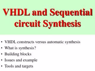
Lecture 21: VHDL, Multiplication, I/O. Soon Tee Teoh CS 147. VHDL. VHDL and Verilog HDL are the two most widely-used hardware description languages. VHDL stands for VHSIC Hardware Description Language. VHSIC stands for Very High Speed Integrated Circuit.

E N D
Lecture 21: VHDL, Multiplication, I/O Soon Tee Teoh CS 147
VHDL • VHDL and Verilog HDL are the two most widely-used hardware description languages. • VHDL stands for VHSIC Hardware Description Language. • VHSIC stands for Very High Speed Integrated Circuit. • Describe a logic circuit by function, data flow behavior and/or structure • Structure and behavior are complementary ways of describing a system. • However, same behavior can be accomplished by different structure
VHDL Blocks • ENTITY block: Describes the interface for the design. Defines the input and output logic signals of the circuit. • ARCHITECTURE block: describes the internal operation of the design. • VHDL allows user to specify • Components of a circuit • Interconnection between components • Many packages also allow user to input state diagram and translate to VHDL code
Simulation and Synthesis • Simulation tests if the logic works • Synthesis takes into account timing considerations. User specifies the propagation delay of a component.
ENTITY block example entity half-adder is port ( a, b: in bit; sum, carry: out bit); end half_adder entity ALU32 is port ( A, B: in bit_vector( 31 downto 0); F: out bit_vector( 31 downto 0); FS: in bit_vector ( 3 downto 0); V, C, N, Z: out bit); end ALU32
ARCHITECTURE block example architecture half_adder_arch of half_adder is begin sum <= (a xor b) after 5 ns; carry <= (a and b) after 5 ns; end half_adder_arch;
Putting components together (1):Example from Weijun Zhang (UCR) First, define two components, OR_GATE and AND_GATE. entity AND_GATE is port( A: in std_logic; B: in std_logic; F1: out std_logic ); end AND_GATE; architecture behv of AND_GATE is begin process(A,B) begin F1 <= A and B; end process; end behv; entity OR_GATE is port( X: in std_logic; Y: in std_logic; F2: out std_logic ); end OR_GATE; architecture behv of OR_GATE is begin process(X,Y) begin F2 <= X or Y; end process; end behv;
Putting components together (1):Example from Weijun Zhang (UCR) Then, define a new entity, comb_ckt, that uses one instance of OR_GATE and one instance of AND_GATE. entity comb_ckt is port( input1: in std_logic; input2: in std_logic; input3: in std_logic; output: out std_logic ); end comb_ckt; architecture struct of comb_ckt is component AND_GATE is port( A: in std_logic; B: in std_logic; F1: out std_logic ); end component; component OR_GATE is port( X: in std_logic; Y: in std_logic; F2: out std_logic ); end component; signal wire: std_logic; begin Gate1: AND_GATE port map (A=>input1, B=>input2, F1=>wire); Gate2: OR_GATE port map (X=>wire, Y=>input3, F2=>output); end struct;
Simulation architecture TB of CKT_TB is component comb_ckt is port( input1: in std_logic; input2: in std_logic; input3: in std_logic; output: out std_logic ); end component; -- declare all I/O ports from unit under test as signals. -- signals are usually declared within architecture signal T_input1, T_input2, T_input3, T_output: std_logic; begin U_UT: comb_ckt port map (T_input1,T_input2,T_input3,T_output); process variable err_cnt: integer := 0; We want to test comb_ckt, which we built in the previous page. So, we load it into our test-bench. continue …
Simulation begin -- Test case 1 T_input1 <= '0'; T_input2 <= '0'; T_input3 <= '0'; wait for 10 ns; assert (T_output=((T_input1 or T_input2) and T_input3)) report "Failed Case1!" severity error; if (T_output/=((T_input1 or T_input2) and T_input3)) then err_cnt := err_cnt +1; end if; -- Test case 2 T_input1 <= '1'; T_input2 <= '1'; T_input3 <= '1'; wait for 10 ns; assert (T_output=((T_input1 or T_input2) and T_input3)) report "Failed Case1!" severity error; if (T_output/=((T_input1 or T_input2) and T_input3)) then err_cnt := err_cnt +1; end if; end process; end TB; Set the inputs In the waveform simulation, watch the signals T_input1, T_input2, T_input3 and T_output.
How to Simulate • Load the circuits into a VHDL simulator. • Example of VHDL simulator: Symphony EDA • Compile the VHDL files. • Run the simulation.
Multiplication Assume multiplying unsigned numbers Multiplicand 1 0 1 0 1 1 0 X 1 0 0 0 1 0 1 1 0 1 0 1 1 0 1 0 1 0 1 1 0 1 0 1 0 1 1 0 1 0 1 1 1 0 0 1 0 1 1 1 0 Multiplier Product Same method as multiplication in decimal: Shift multiplicand to the left. Whenever there is a 1 bit in the multiplier, add the shifted multiplicand to the product.
Multiplication Circuit Initializer Multiplicand Zero Fill More Sig 32 64 32 6 32 Multiplier 64-bit left shift register 32-bit right shift register Down counter register 64 64 6 64-bit adder Zero Detect 64 All 0s 64 64-bit register Bit0, the least significant bit Write enable The initializer begins by putting the Multiplicand in the left shift register, the Multiplier in the right shift register, the number 32 in the down counter register, and the number 0 in the Product register. Product Done
Input/Output • Program and data need to be input. • Results from computation need to be recorded or displayed. • Examples: Keyboard, monitor, printer, hard disk, CD-ROM, network, speakers, microphones
Memory-mapped I/O • Common data, address and control buses for both memory and I/O. • Interface units and memory have distinct addresses. • CPU read and write from interface units as if they were assigned memory addresses. Can use same memory read/write instructions.
Communication between I/O Device and CPU • Common methods: • Polling • Interrupt-driven • DMA
Direct Memory Access (DMA) • Sometimes need to transfer data between I/O device and memory. • e.g. transfer data between memory and hard disk • Don’t involve the CPU so that the CPU can simultaneously execute other instructions. • Method: • DMA Controller sends signal to CPU to request control of Address and Data buses. • CPU disconnects from Address and Data buses, and sends signal to DMA Controller to go ahead • DMA Controller transfers data to/from memory using the Address and Data buses. (At this time, CPU can execute any instructions that does not involve memory read/write) • When DMA Controller is done, DMA Controller signals to CPU • CPU regains control of Address and Data buses, and can now communicate with the memory. • Problem with DMA: The stale data problem or coherency problem: • When device writes to memory directly, cache data is no longer valid • In write-back cache, when CPU writes to cache, data in memory accessed be device is invalid
Hard Disk • A hard disk is used to store data. It is intermediate-speed, nonvolatile and writable. • A hard disk has many platters. • Each platter can be magnetized on one or both surfaces. • There is one read/write head per recording surface. head platter
Hard Disk • Each platter is divided into concentric tracks. • The set of tracks at the same distance from the disk center on all platter surfaces is called a cylinder. • Each track is divided into sectors containing a fixed number of bytes. • In modern, high-capacity disks, there are more sectors in the longer outer tracks. Also, some sectors are reserved to replace defective sectors. sector cylinder track
Hard Disk Timing • The read/write head is used to access data. The set of heads are mounted on actuators that move the heads radially over the disk. • To access data on the hard disk, several steps need to be performed. • First, we need to move the heads from the current cylinder to the desired cylinder. The time taken to do this is called the seek time. • Second, we need to rotate the disk to reach the desired sector. The time taken to do this is called the rotational delay. • Third, some time is needed by the disk controller to access the data. This time is called the controller time. • Finally, the data is read. The rate at which data is read is called the disk transfer rate.
Hard Disk Timing • Typical times: • Seek time: 10 ms • Rotational delay: 6 ms • Controller time: negligible • The total time required to locate a word on the disk is called the disk access time. • Disk access time = Seek time + Rotational delay + Controller time • Typical disk transfer rate: 3 MB/s • Exercise: • The processor wants to load 1 MB of contiguous data from disk to memory. Suppose that the seek time is 10 ms, rotation delay is 6 ms, controller time is 0 ms, and the disk transfer rate is 3 MB/s. How much time does it take?
RAID (Redundant Array of Independent Disks) • Reliability and availability of data • What happens when hard disk fails? Data is lost. • Solution: Use RAID • Use array of hard disks instead of only one. • RAID has several levels. • RAID Level 1: Mirroring. • Simply keep a duplicate of each disk. • Example: 8 disks + 8 duplicate disks • When one disk fails, repair by copying from duplicate disk • How to detect disk failure: There is usually hardware on disk itself to detect that it has failed.
RAID Level 3 • RAID Level 3 is bit-interleaved parity. • Example: 8 disks + 1 parity disk • 8 disks contains data. A bit in the parity disk is set to 1 if the number of 1 bits in the same position in the 8 disks is odd. The parity bit is set to 0 otherwise. • When disk fails, the parity disk together with the 7 surviving disks can be used to reconstruct the failed disk. • Out of the 9 disks, only one can fail at a time. If two or more disks fail at the same time, the failure is not recoverable. • How to protect against simultaneous multiple disk failures? • RAID 6 can handle up to 2 simultaneous failures. It uses a P+Q (Reed-Solomon) coding scheme. • Otherwise, we can also use a 2D array of disks, with a parity disk for each row, and a parity disk for each column.