Download
1 / 32
330 likes | 461 Views
K. steerer. position monitor. Laser. profile monitor. RF pulse compression. 2 x 45 MW. beam dump. 10. 20. 25. 25. quadrupoles. 17 MV/m acceleration. 17 MV/m acceleration. 15 MV/m compression. rf gun cavity. focusing coils. LIL sections. RF deflector. spect. magnet.

E N D
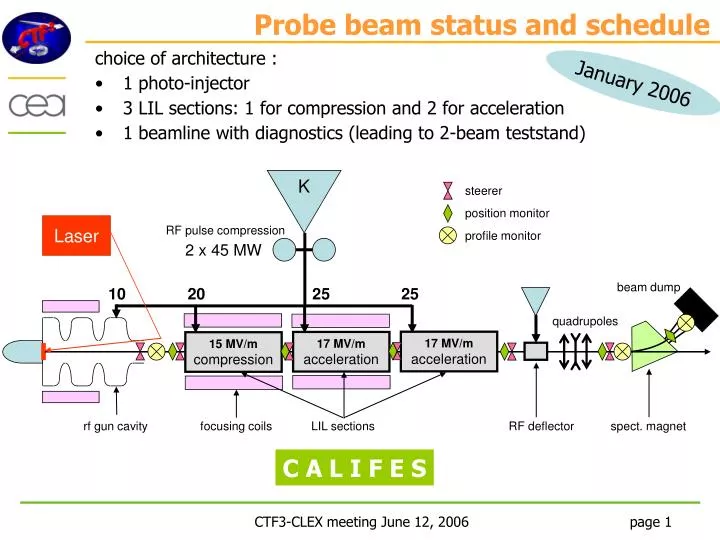
K steerer position monitor Laser profile monitor RF pulse compression 2 x 45 MW beam dump 10 20 25 25 quadrupoles 17 MV/m acceleration 17 MV/m acceleration 15 MV/m compression rf gun cavity focusing coils LIL sections RF deflector spect. magnet Probe beam status and schedule • choice of architecture : • 1 photo-injector • 3 LIL sections: 1 for compression and 2 for acceleration • 1 beamline with diagnostics (leading to 2-beam teststand) January 2006 C A L I F E S
RF gun status R. Roux July, 7th 2006 • Drawings, overview • What is under way? • Open questions, ask for info • Problems, risks
1. Overview • Studies finished • Drawings finished • List of components: • - gun with a measurement loop • - 2 tapered waveguides • - 2 LIL flanges • - 2 solenoids • - 1 steerer • - vacuum chamber (tubes, valve, bellow) • - 2 gauges • - 1 ionic pump • - 1 pneumatic valve • - 1 translation trolley for the preparation • chamber (additional request from CERN) • - NEG coating on the vacuum chamber • (agreed with CERN people) RF input photocathode steerer valve solenoids vacuum pump
2. What’s under way? • Gun: new supplier, the coupler cell should arrive between 17th-21th July • if everything OK, order the rest of the gun, all pieces in September • then, RF measurements, mechanical adjustments and brazing at LAL • (thanks to Eric Chevallay for the 316LN stainless steel, we will soon refunded) • Magnetism: coils and steerer are ordered, should arrive in the beginning of September • power supplies will be bought by CERN (offer of R. Losito) • Vacuum: gauges and valve are received, ionic pump at the end of July • power supply will be bought by CERN (offer of R. Losito) • Mechanics: vacuum chamber and supports are under construction in LAL workshop • it should be finished in September but risks of overlap with PHIN gun • machining PHIN gun has the priority !
3. Open questions, ask for info • Girder: if we can reuse the LIL 2300 mm girder, we need the drawings • open question: RF gun assembly on girder at LAL or at CERN ? • Cabling: Who does the cabling between the photo-injector and the racks? • -cables for solenoids and steerer (electric and cooling) • -cable for RF loop • -cables for gauges and power supply • -on which side of the linac set the connectors of the solenoids? • Possible overlap between the solenoid connectors and RF network pumps? • (happened on PHIN, solenoids sent back to the supplier to modify connectors) • Cooling: tuning cooling loop from frozen water (20°C) • the gun will be mechanically deformed in such a way that • the right tuning frequency achieved at 30°C
3. Problems, risks - New supplier for the gun, if not good delay - Money: 70 k€ received this year not enough to order the power supplies and gun cooling loop I hope to get the totality of the required budget next year in March But up to now, RF gun construction proceeds well
Laser system • Signal taken from the Drive Beam Laser • 2 main distinct tasks: • extraction & manipulation of laser beam (windowing, x4 frequency multiplication, doubling of the pulse frequency 1.5 3 GHz) • transport of the laser beam over 80 m as far as the photo-cathode • Subcontractor : LILM (Laser Matter Interaction Lab) from CEA-Saclay • Study of the 2 tasks till the end of 2006 • mechanical design and realization follow-up by Dapnia • Pb : delay of the DB laser 1st tests with real laser will be very late
Beam dynamics calculations nearly complete ... • single bunch is fine • multibunch operationdue to beam-loading, bunch charge should be linearly reduced to meet energy & phase requirements (1% and 1deg)Qb < 5nC/N • still to be done: • effect of laser spot misalignment • estimation of the emittance measurement accuracy
Califes Drawings Drawings nearly complete ...
Injection beamline BPM screen LIL section input vacuum pump laser table laser beam injector (LAL Orsay)
inter-section steerer BPM
diagnostics beamline total length (cathode plane to output valve) = 21.316 m screen RF deflector QL3 Triplet vac. pump Dipole Dump
RF system klystron, RF pulse compression, RF network : supplied by CERN Modulator : includes • a high voltage pulsed power supply with negative polarity • three electromagnet power supplies • a filament heater power supply • an ion pump power supply • a hydraulic network • a X-ray shielding • a control-command system • some racks containing the materiel offers from vendors received on 1st of July realization time 12-14 months vendor choice at end of July
RF network defined in March 2006 1 power phase-shifter has to be developed (fine tuning of thecompression section)
Phase-shifter 3 GHz scaling from a SLAC model at 11.4 GHz by Alexej Grudiev sliding circular guide + mode converter tolerances and mechanical studymade at Saclay fabrication will start end of september power tests at CERN
RF Gun Vacuum adaptation and laser miror Compression LIL section Accelerating LIL section Accelerating LIL section Diagnostic line IZ 270 IZ 270 IZ 120 IZ 120 IZ 120 IZ 120 IZ 120 IZ 120 Sector 3 Sector 1 Sector 2 Vacuum Vacuum system defined 2 LIL sections tested under vacuum at Cern primary pumping group • 3 valves • 6 ion pumps for LIL sections • 2 ion pumps for input and output beamlines • power supplies, gauges hardware provided by CERN
Magnets QL3 BHZ36
Power supplies requirements Specifications of Power supplies have been done and conveyed to CERN
BPM • Specifications : single bunch & multi-bunch operation (1-64 @ 3 GHz) 0.5 nC • coaxial reentrant cavity, original design from R. Bossard (CERN) • proposed and developed for TTF (M. Luong, C. Simon - DAPNIA) prototype for technology validation : OK pre-serie (2 units) : under fabrication
Beam profile monitors • 3 profiler systems to different locations:injector output, behind the triplet, behind the dipole • 2 main sub-systems: • the vacuum tank with devices (screen, actuator, viewport, lighting) • the optics system (lenses, CCD camera, filter wheel, shielding…) Tank study has started ... Screen holder Insertion mecanism
Optics system TTF2 CTF3 SOLEIL optics design (various magnifications) + CCD camera (with Cern MTV interface) examples of optics design with different levels of integration Califes : will start next September
Derived from SOLEIL(100 MeV, 0.5 to 8 nC, 3 Hz) Adaptation for CALIFES in progress (200 MeV, 1.5 A, 21 ns, 5 Hz) Lead Polyéthylène Graphite 500 Beam Beam Dump
41.6 m 22 m CLEX building CALIFES should fit into CLEX building ... • the last dipole could include 3 branches: • straight to 2-beam teststand • 15° to Beam Dump • 30° to Instrumentation Test Beam
Questions List Can we have a closed area for Califes ? Which girders can we re-use from CERN ? Who does the cabling between the Califes components and the racks ? Alignment: studied by Michel Fontaine from Dapnia who is the CERN contact person ?