Download
1 / 13
130 likes | 257 Views
Modelling of the Effects of Return Current in Flares. Michal Varady 1,2 1 Astronomical Institute of the Academy of Sciences of the Czech Republic 2 J.E. Purkyně University, Ústí nad Labem, Czech Republic. RHD Seminar - Ondřejov 10th March , 200 5. Outline. Motivation

E N D
Modelling of the Effects of Return Current in Flares Michal Varady1,2 1Astronomical Institute of the Academy of Sciences of the Czech Republic 2 J.E. Purkyně University, Ústí nad Labem, Czech Republic RHD Seminar - Ondřejov10th March, 2005
Outline • Motivation • Role of nonthermal electron beams in flares • Main processes controlling non-thermal electron beam dissipation • Physics of RC • Test Particle Code – implementation • Implementation of ohmic RC into TPC • Comparison of energy losses with and without RC • Ohmic or runaway RC? • Preliminary conclusions
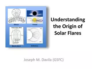
Motivation We want to obtain more realistic heating functions for our hybrid RHD calculations Flare model • Propagation and energy losses of non-thermal electron beams through the solar atmosphere– TPC • Response of originally hydrostatic VAL C atmosphere to the energy deposited by the electron beam – HDC 3. Using time evolution of temperature, density, and energy deposit on hydrogen, time evolution of hydrogen ionisation and hydrogen line profiles evolution profile can be calculated – time dependent non-LTE RTC
Non-thermal Electrons in Flares • Role of non--thermal electrons • energy transport from the reconnetion • site to the lower layers • heating of lower layers via dissipation of • their kinetic energy • Results from hard X--ray observations • non--thermal bremsstrahlung observed • from the footpoints or above the tops of flare • loops – sites of non- thermal electrons • deceleration of acceleration • the distribution function of non--thermal • electrons -- powerlaw • typical energies E0=10-50 keV upper limit of • order100~keV • energy fluxes up to 1012 erg cm-2 s-1
Main Processes of Electron Beams Dissipation Coulomb collisions of non-thermal electrons with cold partly ionised target • good theoretical background describing energy dissipation and scattering (Emslie 1978, Bai 1982) • generally used in HD flare models - approximate analytic formulas assuming constant ionisation in the atmosphere (Emslie, 1978) Energy losses due to electric field generated by the RC • never used in HD flare models - doesn't exist any simple analytic approach Energy losses due to collective plasma processes (plasma waves, turbulence, etc.) • never used in HD flare models - doesn't exist any simple analytic approach
Physics of the Return Current Transport of electron beams of enormous energy fluxes inevitably leads to the existence of huge electric currents which have to be neutralised by return current: Possible modes of RC: • ohmic RC– slow motion of electrons in the atmosphere controlled by collisions with ions –Ohm’s law the electric field accelerates the electrons in the solar atmosphere (creates the RC) and at the same time it decelerates the non-thermal electrons • runaway RC – fast collisionless electrons – Ohm’s law not valid
Test Particle Code - TPC Implementation: • power law energy spectra implemented using energy bins (typically from 10 to 30) in energy range 30 – 100 keV– initiated at the beginning of the run • in each timestep and bin TP with random energy within the bin is initiated • each TP represents a big number of electrons, the number for each bin gives required power law in energy • in a timestep TPs from each bin are moved and a new serie of test particles is initiated • positions, energies and pitch angles of all test particle with non-zero energy are followed in each timestep • energy losses calculated on a fine(N~105) equidistant grid • after a TP is stopped (all its components in all energy bins) it is recycled in order to save RAM Included physics: • energy losses and scattering via Coulomb collisions • ohmic return current – energy losses and influence on pitch angle
Implementation of Ohmic RC into TPC RC calculation • for each grid cell number of electrons passing given cell in a time step ~10-4 s is calculated • this is done in typically 100 consecutive timesteps mean value calculated – smoothing (last value forgotten and replaced by new in each timestep) • RC interpolated to much coarser (N~ 103) RC grid – smoothing RC energy losses • from j and s electric field calculated • then energy loss and pitch angle change can be obtained from change of parallel velocity comp.
Energy Deposit with and without RC _____ total edep _ . _ . RC edep ……. el. Edep - - - - neut. edep. E0 = 30 keV,
Energy Deposits for Different Fluxes and d F = 1010 erg cm-2 s-1, d=3 F = 1011 erg cm-2 s-1, d=3 F = 108 erg cm-2 s-1, d=3 F = 108 erg cm-2 s-1, d=7 F = 1010 erg cm-2 s-1, d=7 F = 1010 erg cm-2 s-1, d=7
Ohmic or Runaway RC? F = 101! erg cm-2 s-1, d=3 Criterion: • Dreicer field • the ratio of RC field to the Dreicer field scales like problems can be in the corona (low electron density, highest current) • even for ratios ~0.2 10% of background electrons are runaway (Norman & Smith 1978) Is it everything wrong? F = 1010 erg cm-2 s-1, d=3
Preliminary Conclusions • The RC energy losses dominate the Coulomb collisions energy losses even for medium energy fluxes. • The stopping depth decreases with increasing energy flux. The main contribution of energy deposit is situated into the t ransition region and corona – possible problems with HD • Electron beams with energy fluxes above F ~ 1011 erg cm-2 s-1are super-dreicer, so it is impossible to use simple calculations based on validity of Ohm’s law. • It is impossible to perform detailed kinetic calculations to obtain RC distribution function in the frame of flare models. Probably some estimates on the ratio between ohmic and runaway RC could be used. • The effect of RC on H lines formation will probably not be negligible.
What to Do? The ratio of runaway electron to electron density is: If the mean velocity of runaway electrons is estimated the runaway current can be Calcutated and than new value of RC electric intensity can be calculated….