Download
1 / 34
910 likes | 1.65k Views
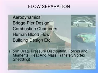
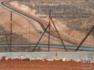
Separation Distance. Proximity between the telecommunication line and the down conductor. Telecommunication line. Faulty installation Separation distance?. s?. s?. Separation distance s Problematic installation of metal lines. s. e.g. e.g. electric line. l.

E N D
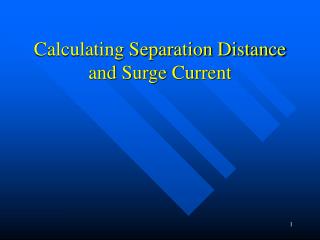
Separation Distance Separation Distance
Proximity between the telecommunication line and the down conductor Telecommunication line Separation Distance
Faulty installationSeparation distance? s? s? Separation Distance
Separation distance sProblematic installation of metal lines s e.g. e.g. electricline l Ref.: IEC 62305-3:2006; Annex E, Figure E.38 Separation Distance 06.10.09 / S6047e
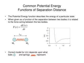
Electrical insulation of the external LPS IEC 62305-3:2006, 6.3 “The electrical insulation between the air-termination or the down-conductor and the structural metal parts, the metal installations and the internal systems can be achieved by providing a distance d between the parts greater than the separation distance s‘: ki depends on the selected class of LPS (see Table 10); kc depends on the lightning current flowing on the down conductors (see Table 11); kmdepends on the electrical insulation material (see Table 12); l is the length, in metres, along the air-termination or the down-conductor, from the point where the separation distance is to be considered, to the nearest equipotential bonding point.“ kc s = ki l km Separation Distance
Insulation of the external LPSValues of coefficients ki and km Class of LPS ki I 0.08 II 0.06 III and IV 0.04 Material km Air 1 Concrete, bricks 0.5 DEHNiso* spacer / Combi 0.7 NOTE 1 When there are several insulating materials in series, it isgoodpracticetousethelowervaluefor km. NOTE 2 The use of other insulating materials is under consideration. Ref.: IEC 62305-3:2006, 6.3, Table 10 + 12 *DEHNiso value stated by DEHN + SÖHNE (Dr. Zischank VAZ) Separation Distance
Separation distanceCoefficient kc for an air-termination rod kc = 1 Individual air-termination rod S Ref.: IEC 62305-3:2006, Annex C, Figure C.1 Separation Distance
Formulas for the calculation of the partitioning coefficient kc 3 • h + c • kc = ———— • 2h + c 1c kc =+ 0,1 + 0,2 2n h Formula for the calculation of the partitioning coefficient kc in case of two down conductors and a type B earth-termination system Basic formula for the calculation of the partitioning coefficient kc Legend: n Total numberof down conductors c Distanceof a down conductortothenext down conductor h Spacing (orheight) between ring conductors Ref.: IEC 62305-3:2006, Annex C, Figure C.2 Separation Distance
Formulas for the calculation of the partitioning coefficient kc 1 n National specification for the partitioning coefficient kc for buildings with “meshed“ air-termination system From the point of proximity to the 1st node kc1 = 1 • From the 1st node to the next node • in case of two outgoing lines kc2 = 0.5 • in case of three outgoing lines kc2 = 0.33 • in case of four outgoing lines kc2 = 0.25 Every further node reduces the kc value* by half * NOTE: The valueshould not besmallerthan Separation Distance
Calculation example of the separation distance sBuilding with gable roof, class of LPS III 3 1c kc =+ 0.1 + 0.2 2n h h = 6 m Calculation according to IEC 62305-3 c = 14 m Number of down conductors: 4 l = 12 m 8 m Separation Distance
Calculationexampleoftheseparationdistance sBuildingwith gable roof, classof LPS III 3 1 3 14 kc = + 0.1 + 0.2 = 0.490 2 4 6 1c kc =+ 0.1 + 0.2 2n h Calculation of kc according to IEC 62305-3 n = 4 Total number of down conductors h = 6 m Height or spacing of the ring conductors, gutter c = 14 m Max. distance between two down conductors Separation Distance
Calculation example of the separation distance sBuilding with gable roof, class of LPS III 0.490 s = 0.04 12 m = 0.47 m 0.5 Calculation of s according to IEC 62305-3 Coefficient class of LPS III:ki= 0.04 Partitioning coefficient: kc = 0.490 Material used for the isolating distance Brick: km= 0.5Length along the air-termination conductor / down conductor: l= 12 m kc s = ki l (m) km Separation Distance
Calculation example of the separation distance sBuilding with gable roof, class of LPS III 0.490 s = 0.04 17 m = 0.66 m l = 17 m 0.5 Calculation of s according to IEC 62305-3 Number of down conductors: 4 Lamp • Lamp • Conductors • Heating • Water ... 14 m 8 m Separation Distance
Separation distance - Example 2.2 km = solid materialAir-term. rodconnectedtwicetothemeshnetwork Class of LPS II Height of the building h / length l to the earth-termination system: l = 8m Mesh size: 10m x 10m Number of down cond.: n = 24 Min. value for kc: = = 0.042 1 1 n 24 Roof superstructure h = 2m s = ki (kc1·l1 + kc2·l2 + ... + kcn·ln) / km = s = 0.06 (0,5 · 8m + 0.25 · 4m + 0.125 · 10m + 0.063 · 10m + 0.042 ·8m) / 0.5 = s = 0.87m for solid material s Air-termination rod kc6=0.042 l6 = 8 m kc5=0.063 l5 = 10 m kc4=0.125 l4 = 10 m kc2= 0.5 l2 = 8 m 20 m kc3= 0.25 l3 = 4 m Roof superstructure kc2= 0.5 l2 = 8 m l=10m Separation Distance
Nodal analysis - Software for the determination of the separation distance s = node Every line is shown as a resistor. The voltages of the nodes, i.e. the difference between the node potentials, are calculated by means of the supply of a defined lightning current and the mathematical solution of the equation. I R1 R2 R3 R4 R5 R6 R7 R8 R9 R10 R11 R12 R13 R14 R15 R16 R17 0V 0V 0V 0V Separation Distance
Model for the determination of current division Nodal analysis Separation Distance
Spearartion distance calculated according tonodal analysis DEHN Distance Tool Start software Separation Distance
DEHNconductorHVI® Conductor Technology Fields of Application
Basic development of a creepage discharge at the HVI conductor with special coating Proximity to earthed metal parts EB connection via earthing clamp Inner conductor HVI conductor with special coating Insulation, semiconducting Separation Distance
Coaxial Cables with Field Control andConductive Shield as insulated Down-conductors Connection with the air termination Field control Conductive shield (e.g. braided copper) Induction of the lightning current (feeding point) conductor HV-Insulation External coating (weather and UV resistant) HVI-Seminar HVI-Leitungen
Basic illustration of the structure of an isolated down conductor with semiconductive coating sealing unit area semi- conductive coating connection to equipotential bonding connection to the air-termination system incoming lightning impulse current inner conductor high-voltage resistant isolation Lit.: HVI-Seminar HVI-Leitungen 11.12.03 / 3465
DEHNconductor system, HVI® conductor I Head piece Fixed EB element Earth connection Sealing end section HVI conductor I Part No. 819 020 Conductor holder Part No. 275 120 EB clamp Part No. 405 020 Conductor length has to be specified Earth connection element (removable) Separation Distance
Installation of the different types of HVI® conductors HVI® conductor type II HVI® conductor type III EB connection EB connection Sealing end Sealing end HVI® conductor II, fixed length,secong sealing endfixed HVI® conductor III, can be cut to length, second sealing end has to be mounted HVI® conductor type I Sealing end EB connection Separation Distance
Isolate air-termination system for mobile radio stations DEHNconductor system HVI® conductor Air-termination tip GRP supporting tube Aluminium supporting tube No metal parts may be installed in the sealing end section! EB element HVI® conductor Source: Bischof-Blitzschutz, Weyhe Separation Distance
Grey HVI® conductor installed in the supporting tube with integrated sealing end and air-termination tip Air-termination rod GRP supporting tube Aluminium supportingtube HVI conductor HVI® conductor I Part No. 819 323 HVI® conductor II Part No. 819 324 HVI® conductor III Part No. 819 325 Separation Distance
Voltage-controlled insulated down conductorSeparation distance is maintained Insulated HVI® conductor I a Isolated air-termination system metal capping of the parapet located in the protection area of an isolated air-termination system is connected to equipotential bonding Sealing end Equipotential bondingconnection Metal roof superstructure Reinforcement Separation distance s Cable duct Equivalent separation distance of the HVI conductor: s = 0.75 m in air s = 1.50 m for solid material Cable duct Foundation earth electrode Separation Distance
Isolated Lightning Protection Air-Termination Masts and HVI Conductor Light
DEHNconductor system / HVI® conductor light HVI conductor light Prerequisite for the use of HVI conductors light: Separation distance 0.45 m (in air) Equiv. separ. distance s 0.45 m (in air) 0.90 m (solid material) Core Copper (soft) Cross-section 19 mm² Insulation PE (polyethylene) Outer diameter 20 mm (black sheath 17 mm) Colour Dark grey Disposable reel made of plywood (Ø approx. 80 cm), width approx. 50 cmTotal weight approx. 66 kg Length 100 m on a reel: Part No. 819 125 Separation Distance
Isolated lightning protection systemHVIÒ conductor light, class of LPS III Detail A air-terminat-ion mast Detail A air-termination mast HVI conductor light 15 m 18.1 m 30 m Separation Distance
Isolated lightning protection systemHVIÒ conductor light, class of LPS III 27 m 1.5 m 1.5 m Protection area Protection area 1.90 m HVI conductor light 20 m Protection area Protection area 30 m Separation Distance
DEHNconductor system / HVI® conductor light Isolated air-termination system, air-termination mast No electrically conductive or earthed parts may be located in this protection area! SET I Air-termination tip 1000 mm total height 2900 mm, with supporting tube and tripod Air-term. tip 1m s adjustment range approx. 140 cm Separation Distance
DEHNconductor system / HVI® conductor light Isolated air-termination system, flat roof SET II Air-termination rod 2000 mm total height 3900 mm, with supporting tube and tripod Air-term. rod 2m Separation Distance
DEHNconductor system / HVI® conductor light Isolated air-termination system, flat roof Connecting plate with 4 connection possibilities Separation Distance