Download
1 / 56
560 likes | 642 Views
application transport network data link physical. application transport network data link physical. application transport network data link physical. network data link physical. network data link physical. network data link physical. network data link physical. network

E N D
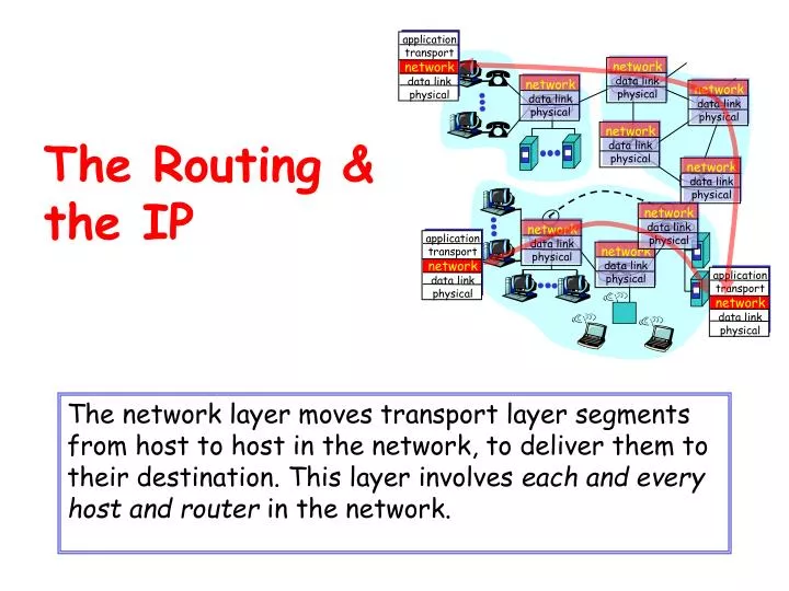
application transport network data link physical application transport network data link physical application transport network data link physical network data link physical network data link physical network data link physical network data link physical network data link physical network data link physical network data link physical network data link physical The Routing &the IP The network layer moves transport layer segments from host to host in the network, to deliver them to their destination. This layer involves each and every host and router in the network.
transport packet from sending to receiving hosts network layer protocols in every host, router three important functions: path determination: route taken by packets from source to destination - routing algorithms switching: move packets from router’s input to appropriate router output call setup: some network architectures require router call setup along path before data flows (connection oriented networks) network data link physical network data link physical network data link physical network data link physical network data link physical network data link physical network data link physical network data link physical application transport network data link physical application transport network data link physical Network layer functions
no call setup at network layer routers: do not maintain state for the end-to-end connections no network-level concept of a “connection” packets are typically routed using only destination host ID which is carried in the packet packets between same source-destination pair may take different paths application transport network data link physical application transport network data link physical Datagram networks: the Internet model 1. Send data 2. Receive data
Graph abstraction for routing algorithms: graph nodes are routers graph edges are physical links link cost: delay, distance, # of hops, rate structure or congestion level = $$ Other costs?? 5 3 5 2 2 1 3 1 2 1 A D E B F C Routing protocol Routing Goal: determine a “good” path (sequence of routers) thru the network from the source to the destination • “good” path: • typically means minimum cost path • other definitions also possible
scale: with 55 million+ destination hosts: can’t store all destinations in routing tables! routing table exchange would swamp links! administrative autonomy internet = network of networks each network admin may want to control routing in its own network Hierarchical Routing Our routing study thus far – an idealization • all routers are identical • the network is “flat” … not true in practice Why?
aggregate routers into regions,called “autonomous systems” (AS) routers in same AS run same routing protocol “intra-AS” routing protocol routers in different AS can run different intra-AS routing protocol special routers in AS run intra-AS routing protocol with all other routers in AS also responsible for routing to destinations outside AS run inter-AS routing protocol with other gateway routers gateway routers Hierarchical Routing
Internet AS Hierarchy Inter-AS border (exterior gateway) routers Intra-ASinterior (gateway) routers
Internet inter-AS routing: BGP • BGP (Border Gateway Protocol):thede facto standard • Path Vector protocol: • similar to Distance Vector protocol • each Border Gateway broadcasts to neighbors (peers) the entire path (I.e, sequence of ASs) to destination
b a a C B d c A b b a c A.a A.c C.b B.a Intra-AS and Inter-AS routing • Gateways: • perform inter-AS routing amongst themselves • perform intra-AS routers with other routers in their AS network layer inter-AS, intra-AS routing in gateway A.c data link layer physical layer
Inter-AS routing between A and B Host h2 b a a C c B b d Intra-AS routing within AS B A b a c Host h1 Intra-AS routing within AS A A.a A.c C.b B.a Intra-AS and Inter-AS routing • We’ll examine specific inter-AS and intra-AS Internet routing protocols shortly
IP address: 32-bit identifier for host or router interface interface: connection between host or router and the physical link routers typically have multiple interfaces hosts typically have only one IP addresses are associated with the interface, not the host or the router 223.1.1.2 223.1.2.1 223.1.3.27 223.1.3.1 223.1.3.2 223.1.2.2 IP Addressing: introduction 223.1.1.1 223.1.2.9 223.1.1.4 223.1.1.3 dotted-decimal notation: 223.1.1.1 = 11011111 00000001 00000001 00000001 223 1 1 1
IP address: network part (high order bits) host part (low order bits) What’s a network ? (from the IP address perspective) device interfaces with the same network part of their IP address hosts can physically reach each other without an intervening router IP Addressing 223.1.1.1 223.1.2.1 223.1.1.2 223.1.2.9 223.1.1.4 223.1.2.2 223.1.3.27 223.1.1.3 LAN 223.1.3.2 223.1.3.1 Example: network consisting of 3 IP networks (for IP addresses starting with 223, the first 24 bits are the network address – more later)
class A network 0 host (24 bits) 27 = 127 networks 224 = 16.8 million+ hosts B network 10 host (16 bits) multicast address (28 bits) 1110 214 = 16,384 networks 216 = 65,536 hosts C network host (8 bits) 110 221 = 2 million+ networks 28 = 256 hosts D 228 = 268.4 million+ hosts IP Addresses Given the notion of a “network”, let’s look closer at IP addresses: “classful” addressing - 1.0.0.0 to 127.255.255.255 128.0.0.0 to 191.255.255.255 192.0.0.0 to 223.255.255.255 224.0.0.0 to 239.255.255.255 32 bits What is the address space size (number of hosts) for each class?
Abbreviated Format of the Address Ranges • The minimum & maximum values of the range: • 11100000.00000000.00000000.000000002 11101111.11111111.11111111.111111112 • E0.00.00.0016 … EF.FF.FF.FF16 • The first part of the abbreviation is the common byte(s) in the range • The second part of the abbreviation is the number of bits, which are common for the all members of the range 224.0.0.0 - 239.255.255.255 224/4
The private address ranges • Used locally • Never used in the Internet • Gateways do not forward the packets addressed to private addresses • The network, which uses the private address range can be connected to the Internet by the NAT (Network Address Translation)
host part network part 11001000 0001011100010000 00000000 200.23.16.0/23 IP addressing: CIDR • classful addressing: • inefficient use of address space, address space exhaustion • e.g., class B network is allocated enough addresses for 65K hosts, even if only 2K hosts exist in that network • CIDR:Classless InterDomain Routing • network portion of address of arbitrary length • address format: a.b.c.d/x, where x is # bits in the network portion of an address
IP addresses: how to get one? Hosts (host portion): • hard-coded by system admin in a file • DHCP:Dynamic Host Configuration Protocol: dynamically get address (RFC 2131): “plug-and-play” • host broadcasts “DHCP discover” msg • DHCP server responds with “DHCP offer” msg • host requests IP address: “DHCP request” msg • DHCP server sends address: “DHCP ack” msg
Why different Intra- and Inter-AS routing ? Policy: • Inter-AS: admin wants control over how its traffic is routed, who routes through its net. • Intra-AS: single admin, so no policy decisions needed Scale: • hierarchical routing saves table size, reduces update traffic Performance: • Intra-AS: can focus on performance • Inter-AS: policy may dominate over performance
Intra-AS Routing • Also known as Interior Gateway Protocols (IGP) • Most common IGPs: • RIP: Routing Information Protocol (legacy) • OSPF: Open Shortest Path First (common) • EIGRP: Enhanced Interior Gateway Routing Protocol (proprietary – Cisco Systems)
Distance-vector routing algorithm (DVR) • The different names of the background mathematical algorithm: • Backward search algorithm • Bellman-Ford algorithm • Goal: search the smallest delay paths for the traffic • For this reason in each router a table is created, which contains: • The interface to the smallest delay path to every node • The estimated delay of each path • This table is called distance vector
Bellman-Ford algorithm Routing tables (Step 1) Distance vector Modified entry Unmodified entry
Bellman-Ford algorithm Step 1 Shortest paths in the routing table of the router A
Routing tables resulted from the previous step Bellman-Ford algorithm Routing tables (Step 2)
Bellman-Ford algorithm Step 2 Shortest paths in the routing table of the router A
Routing tables resulted from the previous step Bellman-Ford algorithm Routing tables (Step 3)
Routing tables resulted from the previous step Bellman-Ford algorithm Routing tables (Step 4)
Bellman-Ford algorithm Step 3-4 Shortest paths in the routing table of the router A
Routing tables resulted from the previous step Bellman-Ford algorithm Routing tables (Step 5)
Bellman-Ford algorithm Step 5 and the final result Shortest paths in the routing table of the router A
Link-state routing algorithm • The different names of the background mathematical algorithm: • Forward search • Dijkstra algorithm • Shortest path (SP) • The SP is the optimal path, however, this is not obviously the geometrically shortest path • Other factor, which can be taken into account: • Number of routers in the path • delay • cost • Average traffic • Reliability of the links in a certain path
Dijkstra’s algorithm • Dijkstra's algorithm, named after its inventor the Dutch computer scientist Edsger Dijkstra, solves a shortest path problem for a directed and connected graph G(V,E) which has nonnegative (>=0) edge weights • Dijkstra's algorithm is known to be a good algorithm to find a shortest path
Dijkstra’s algorithm The method… • Finds the shortest path between a source node and the rest • Finds routes between nodes by cost precedence • Assumes every cost is a positive number • Supports directed or bidirectional communication
Dijkstra’s algorithm Initialisation – Example network
Least cost new node: D Dijkstra’s algorithm Step 1
Least cost new node (with smaller IP address): B Dijkstra’s algorithm Step 2
Least cost new node:E Dijkstra’s algorithm Step 3
Least cost new node: C Dijkstra’s algorithm Step 4
Least cost new node: G Dijkstra’s algorithm Step 5
Dijkstra’s algorithm Step 6 (final result)
Dijkstra’s algorithm Second exampleStep 1
Dijkstra’s algorithm Second exampleStep 2
Dijkstra’s algorithm Second exampleStep 3
Dijkstra’s algorithm Second exampleStep 4
Dijkstra’s algorithm Second exampleStep 5
Dijkstra’s algorithm Second exampleStep 6
Dijkstra’s algorithm Second exampleStep 7
Dijkstra’s algorithm Second exampleStep 8