Download
1 / 46
460 likes | 623 Views
EPICS Detector and Feedback Software. Mark Rivers GeoSoilEnviroCARS, Advanced Photon Source University of Chicago. Outline. EPICS Interface to Canberra Electronics EPICS Interface to XIA DXP Electronics for Energy Dispersive Detectors ccdApp: Generic EPICS Interface to Area Detectors

E N D
EPICS Detector and Feedback Software Mark Rivers GeoSoilEnviroCARS, Advanced Photon Source University of Chicago
Outline • EPICS Interface to Canberra Electronics • EPICS Interface to XIA DXP Electronics for Energy Dispersive Detectors • ccdApp: Generic EPICS Interface to Area Detectors • smartControl: Using Bruker SMART to Control EPICS Experiments • Generic Feedback under EPICS • APS Beam Position Monitor and EPICS Software
mcaApp – support for multichannel analysers • mcaRecord • Like waveform record with lots of additional fields • Start/stop acquisition • Preset live/real time • Regions of interest – total and net counts, can be used as EPICS scan record detector like a scaler • Device independent • Primary device support uses asyn – also device independent • Drivers implement int32, float64, int32array asyn interfaces
mcaApp – support for multichannel analysers • Devices supported • Canberra Ethernet AIM MCAs • Canberra ICB modules (amplifier, ADC, HVPS, TCA, DSP) • SIS multichannel scaler • APS quad electrometer • Acromag IP330 A/D as a transient digitizer (16 channels, ~2kHz) • XIA Saturn (=Radiant Vortex) • XIA DXP-2X
Canberra electronics • AIM Ethernet MCA • Non-TCP/IP protocol • EPICS support uses low-level Ethernet hooks on vxWorks, libnet and libpcap on Linux • Based on library from Canberra for middle layer between asyn driver and low-level I/O • This is a common model for device support. On EPICS the low-level and high level parts need to be written, the middle layer can come from the manufacturer.
IDL MCA Display • mcaDisplay • Full-featured program for displaying, controlling EPICS multi-channel analysers, including peak fitting • Uses epics_mca class library, and exports mca_display class, so it can be controlled by other IDL applications
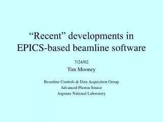
Fast DSP Electronics for EDS Detectors • Digital signal processing based x-ray spectrometers from X-ray Instrumentation Associates (XIA). • Standalone (Saturn) for single-element detectors • CAMAC modules for multi-element detectors. 4 detectors/CAMAC module, very cost-effective • MCA record • Start and stop data acquisition • Readout the spectra • Control and read the data acquisition time • Definine up to 32 Regions of Interest (ROIs) for computing the net or total counts in each fluorescence peak. • DXP record • Provides complete control over the internal operation of the DXP • More than 50 adjustable parameters. • Next generation will be PXI based, rather than CAMAC.
16 element detector VME crate CAMAC crate DXP4C modules
Fast DSP Electronics for EDS Detectors • NEW feature: Saturn detector can be controlled from Linux or Windows running EPICS 3.14 • DXP-2X can be controlled from vxWorks VME crate via VME/CAMAC interface • Software now uses the high-level Handel API from XIA, rather than low-level Xerxes interface • Should work with new X-MAP PXI detector with minimal work
ccdApp: EPICS Interface to Area Detectors • Goal: Uniform interface for controlling area detectors (CCD, online image plates) from EPICS • Any EPICS client (e.g. spec, IDL, scan record) can control (at a bare minimum). • Exposure time • File name • Start collection, wait for completion • Much more control for most detectors • Current status: • MAR 165 CCD (complete, in use on Sectors 1, 8, 13, 18, others) • Roper CCD detectors (complete, in use on Sectors 12, 13, 15, 20) • Bruker CCD detectors • Winview interface complete. In use on Sectors 13 this run. • SMART Service interface in planning stage. To be done? • MAR 345 online image plate (soon) • Will use scan345, but replace file I/O with socket I/O
Implementation • Use manufacturer’s software for primary user interface. • Minimizes amount of new code • Uses existing file formats, unwarping algorithms, etc. • These programs include: • marccd for MAR165 • Winview/Winspec for Roper cameras • WinView for Bruker cameras. • Requires PCI card to replace ISA card that Bruker supplies. Also new SCSI-type cable. • SMART for Bruker cameras • scan345 for MAR 345 image plate
Implementation Control these programs from EPICS Each of these programs has a “remote control” interface, typically using TCP/IP sockets Using EPICS means each client (e.g. spec) does not have to know how to talk to each type of detector. Only has to know how to talk to EPICS. EPICS software consists of Database of records (PVs), identical for all detectors State-notation-language (SNL) programs, unique for each detector. Reads/writes PVs and communicates with remote control interface over sockets. The database and SNL programs are typically run on the same machine that the user interface software runs on (e.g. Linux box for MAR detectors, Windows for Roper and Bruker). No VME crate required.
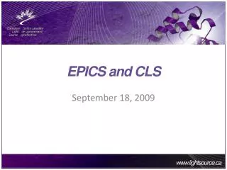
Schematic Architecture EPICS client spec, IDL, scan record, etc. EPICS database Not detector specific ~70 records EPICS SNL program Detector specific CA CA Sockets Manufacturers control program marccd, WinView, SMART, etc. Socket server Typically running on a single machine (not necessary) C calls
“Expert” medm screen Many fields do not apply to all detectors. Simpler screens (e.g. for MAR 165 only) can easily be made.
marccd remote control Acquire/Remote Control dialog
Roper Interface WinView (from Roper) Socket server written in Visual Basic. Simple ASCII commands. Calls COM interface to automate WinView & WinSpec). Not EPICS specific, other applications can talk to it.
smartControl: Interfacing the Bruker SMART Software with EPICS
Introduction • Bruker makes x-ray detector systems for single-crystal and powder diffraction, and small-angle scattering applications. • Widely deployed in crystallography laboratories world-wide • Large user community who are familiar with the Bruker “SMART” control and analysis software. • SMART software is only capable of controlling goniometers through the Bruker General Goniometer Control System (GGCS), which is a specific hardware controller manufactured by Bruker. • GGCS is not generally used to control goniometers at synchrotron facilities. • smartControl permits the standard Bruker SMART software to control any goniometer, with any number of axes, through EPICS. Also provides • Shutter control • Normalization information, such as from an ion chamber, to the SMART software where it is stored in the frame headers.
VME Crate Serial connection PC running SMART diffractometer/detector control program EPICS serial port with Generic Serial Record smartControl State Notation Language Program and database Digital I/O Card Motor controller Shutter Trigger Detector Trigger Detector Diffractometer Bruker shutter controller (stepping motor) Shutter smartControl Architecture
smartControl Implementation • Communicates with GGCS goniometer via RS-232 • Runs in an EPICS IOC and emulates the GGCS. • Listens to commands from SMART on the RS-232 port • Translates those commands into EPICS channel access calls to: • Move goniometer motors • Open and close shutters • Trigger the CCD detector • Start and read scalers and timers for beam intensity normalization • Sends responses back to the SMART system in the format that SMART expects from the GGCS. • Thus, SMART thinks it is talking to a GGCS, while it is actually talking to an EPICS IOC. • Implementation Details • smartControl consists of: • An EPICS database, smartControl.db • A State Notation Language program, smartControl.st • Motor control is done via the EPICS “motor” record. • RS-232 communication is done via the EPICS “asyn” module • Scaler/timer control is done via the EPICS “scaler” record. • Shutter control is done via the EPICS “binary output” record. • Advantages • Any motor with EPICS device support can be used for the goniometer. • Any type of beam monitor (ion chamber, photodiode, etc.) can be used. • Any shutter can be used by simply constructing a simple database with a binary output record controlling it.
smartControl User Interface • Display and manual control of the state of the fast shutter, slow shutter (if implemented), and detector trigger • Setup of the goniometer motors • Each of the (up to) 4 axes that SMART controls is assigned to an EPICS motor. • Existsa\ (Yes/No) • Offset and sign difference between the EPICS motor coordinate system and the SMART coordinate system. • Useful when the same goniometer is used with SPEC and with SMART, since these use different sign conventions. • High and low “cut” that control where the limits of motion of the actual EPICS motor are. • A command from SMART to move omega to +140 degrees can be translated into a move to –220 degrees. • Display of the motor parameters for the goniometer axes from the SMART system’s perspective.
Systems Controlled • Single axis rotation stage for diffraction with SMART 1500 at NSLS X-26A. • Newport 6-axis General Purpose Goniometer at APS Sector 13 with the SMART 1500 and SMART 2K systems. Applications include single-crystal micro-diffraction and single-crystal diffraction in the diamond-anvil cell. • Huber 4-circle goniometer at APS Sector 15 with the SMART 6000 system. Applications include microcrystal and time-resolved diffraction. • Single-axis goniometer (Newport UR-100 stage) at APS Sector 13 with the SMART 2K detector. Applications include single-crystal micro-diffraction and high-temperature, high-pressure powder diffraction in an externally heater diamond-anvil cell.
Many applications for feedback on APS beamlines Dedicated feedback controllers are expensive and relatively inflexible A new EPICS record for performing feedback Enhanced Proportional Integral Derivative (EPID) Flexible and fast feedback under EPICS Closing the Loop: Using Feedback in EPICSMark Rivers, Center for Advanced Radiation Sources
EPID record: Enhancements over the standard EPICS PID record • Separation of device support from the record. • Soft Record device support which uses EPICS database links • Very similar to the PID record • EPID record can also be used with other device support • Communicate with faster feedback software • Hardware controllers. • Device support is provided in the Message Passing Facility for fast feedback (> 1 kHz) using an Acromag IP330 ADC and a Systran DAC128V DAC. • Addition of many fields (OUTL, DRVH, DRVL) to simplify construction of databases
The PID expression is computed as an absolute number, rather than a differential number to be added to the present output value. Simplifies database construction, and also permits the record itself to perform limit checking on the output. Limits are placed on the magnitude of the integral term (I) which are lacking in the PID record. Monitors are posted for the CVAL field Simplifies construction of user-interface tools, such as plotting. The CVL field has been renamed INP This field can now be modified (a feature of EPICS R3.12 and higher) A single EPID record can be used to control different processes at different times. Changed the time units of the KI and KD terms from minutes to seconds
The EPID record has two kinds of device support. “Soft” device support allows the readback input and control output to be any EPICS process variables. Very flexible Any type of device can be used for input (analog to digital converter, RS-232, GPIB, scaler, etc.) Any type of device can be used for output (digital to analog converter, RS-232, GPIB, etc.) Can be reconfigured on the fly, changing the input and outut process variables, feedback coefficients, etc. Limited to standard EPICS scan rates, typically 10 Hz maximum Sufficient for many applications “Slow” Feedback
Input from any driver that supports asynFloat64 with callbacks (e.g. callback on interrupt) Output to any driver that supports asynFloat64. Very fast Up to 10 kHz feedback rate Feedback coefficients and feedback rate be reconfigured on the fly “Fast” Feedback
GSECARS Applications of EPID record • Monochromator second crystal feedback: • Feedback on beam position on 13-ID, using photo-diodes in-vacuum slits, measuring scattered radiation from in-vacuum slits • Feedback on beam intensity on 13-BM, using table-top ion chamber. • Recovers gracefully from beam dumps. PV available to indicate “feedback locked”, which data acquisition programs can wait for. • Position feedback on large Kirkpatrick-Baez mirrors with piezo actuators. Stabilizes beam position at sample. • Furnace temperature control in the large-volume press in 13-BM-D and 13-ID-D. Safety checks to limit voltage, current, and power. • Pressure control in the large-volume press, via hydraulic pump, in 13-BM-D. Can ramp pressure up and down using scan record to control setpoint • Temperature stabilization via laser power control in the laser-heated diamond-anvil cell in 13-ID-D.
Example Application: Monochromator Second Crystal Stabilization
Hardware and EPICS Software for the APS Quad Electrometer for X-ray Beam Position MonitorsMark Rivers (CARS) and Steve Ross(APS) Steve has designed a 4-channel electrometer for measuring currents in the nA to uA range. Intended primarily for reading x-ray beam positions using 4 photodiodes or split ion chambers. Compact and inexpensive, and can be placed close to the position monitor hardware to keep signal leads short. Outputs digital data at up to 815Hz over a fiber-optic cable Read by a pair of VME boards. Fiber allows reliable data transmission over long distances, for example from an experiment station to a VME crate in the FOE, where feedback to a monochromator crystal can be implemented.
Electrometer Hardware Remote ADC unit and battery VME boards
Applications Feedback of the pitch and roll of monochromator crystals based on the beam position in the beamline or experimental station. Feedback on mirror pitch for stabilizing the position of the beam downstream of a focusing mirror. In-vacuum fluorescent foils allow I0, beam position, and energy calibration to always be available Replaces: 4 SRS570 current amplifiers 4 ADCs, or 4 V/F converters and 4 scaler channels
I have developed a EPICS software (quadEM) to read the digital data from the electrometer. Interrupt driven, reads the digital data stream at 815Hz. Provides the current in each of the 4 photodiodes, as well as the sum, difference and position for opposite pairs of diodes. Device support is provided for 3 types of EPICS records: analog input (ai) record at up to 10 Hz multichannel analyzer (mca) record which functions as a “digital scope”, capturing the values at up to 815Hz feedback (epid) record for fast feedback through an A/D converter at up to 815Hz. The mca and epid records can run slower than 815Hz as well, in which case they provide signal averaging. EPICS Software
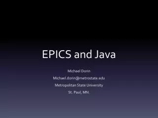
Fiber connection ADCMOD2 quad electrometer VME card1 P2 connection Hardware wire connection VME card2 (PASSTH) IP-Unidig digital I/O card with interrupts quadEM Software 4 photodiodes quadEMScan quadEMSweep quadEMPID mca record ao record ai record EPID record System Architecture VME Crate
Implementation Details • Data comes from the electrometer into the VME system at up to 815Hz. • Current VME boards do not support interrupts • They do put out a TTL pulse when new data arrives, up to 815Hz. • This pulse is input to an IP-Unidig Industry Pack I/O module, which does support interrupts. • IP-Unidig interrupt routines calls the function to read the quad electrometer VME board. • On each interrupt up to 3 quadEM functions are called • quadEMScan averages the current reading and returns averaged readings to EPICS “analog input” records • quadEMSweep puts the current reading into an array for an EPICS “mca” record. Performs averaging if the channel advance time is less than the electrometer clock rate. • quadEMPID uses the current reading to perform fast feedback via a Systran IP DAC. Performs averaging if the feedback rate is less than the electrometer clock rate.