Download
1 / 8
80 likes | 206 Views
DTL Mini Workshop Introduction MV, 12.09.2011. Welcome to all participants (CERN and external) from the Linac4 management. Accelerating structure architecture.

E N D
DTL Mini Workshop Introduction MV, 12.09.2011 Welcome to all participants (CERN and external) from the Linac4 management
Accelerating structure architecture When b increases during acceleration, either the phase difference between cavities Dfmust decrease or their distance d must increase. d = const. f variable d Individual cavities – distance between cavities constant, each cavity fed by an individual RF source, phase of each cavity adjusted to keep synchronism, used for linacs required to operate with different ions or at different energies. Flexible but expensive! Better, but 2 problems: create a “coupling”; create a mechanical and RF structure with increasing cell length. f = const. d variable d bl Coupled cell cavities - a single RF source feeds a large number of cells (up to ~100!) - the phase between adjacent cells is defined by the coupling and the distance between cells increases to keep synchronism . Once the geometry is defined, it can accelerate only one type of ion for a given energy range. Effective but not flexible.
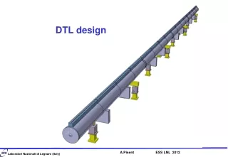
The two main options 1. Sequence of short (1 or 2-gap) cavities, usually superconducting, spaced by quadrupoles. high cost (many RF systems & cav.) can reach CW operation flexible (different ions possible) 2. Drift Tube Linac (sequence of drift tubes with quadrupoles). lower cost (high-power RF system) simple only to duty cycle ~20% (then cost goes up) not flexible (only 1 particle) 3 For the Linac4/SPL section between 3 and 50 MeV, the DTL is the logical choice.
TE mode: CH-DTL Interdigital-H Structure Operates in TE110 mode Transverse E-field “deflected” by adding drift tubes Used for ions, b<0.3 CH Structure operates in TE210, used for protons at b<0.6 High ZT2 but more difficult beam dynamics (no space for quads in drift tubes)
CH used only in FAIR Comparing the 2 most recent linac projects (SNS and JPARC) and the 2 European linacs in construction or close to construction (Linac4 and FAIR): 402 MHz 1.4mA avg. 325 MHz 0.7mA avg. 352 MHz 0.02-2.4mA 325 MHz 5 mA avg. Common features: all designs normal conducting, sequence of different accelerating structures
Comparing DTL and CH The shunt impedance of the CH-DTL is higher, but only below 20 MeV. The special beam dynamics used to overcome the fact that the tubes have no quadrupole (KONUS) leads to higher emittance growth, more sensitivity to errors and probably some beam loss when errors are present, inacceptable for high duty cycle. From: Eds. C PlostinarComparative Assessment of HIPPI Normal Conducting StructuresCARE-Report-2008-071-HIPPI http://epubs.cclrc.ac.uk/bitstream/3705/CARE-Report-08-071-HIPPI.pdf 6
One last candidate Nice poster at IPAC11 from S. Kurennoy (LANL) on an IH design with PMQs inside drift tubes (the best of two worlds, high shunt impedance and clean FODO dynamics?). At the moment, it does not look like a possible candidate for replacing the DTL: Length of 1st drift tube (3 MeV, 352 MHz) is 0.5*bl/2 ≈ 17 mm → the 1st PMQ would be about 15 mm long, with 20 mm aperture … no way. The shunt impedance with large diameter drift tubes is lower, probably higher than DTL only in the first MeV’s (up to 10 MeV?). Drift tubes with quadrupoles need to be more precisely aligned than for the pure IH. 7
History of Linac4 DTL R&D DTL development project started with ITEP Moscow and VNIIEF Sarov on 1.2.2005: construction of a prototype to be sent to CERN for evaluation, to be completed by 31.1.2007 (2 years). In September 2011, 6 years and 8 months later, the prototype is not yet finished. In parallel, start a “DTL Task Force”, with a 1st meeting on 2.12.2004. Idea was to gather CERN experts to develop an alternative design. After a long discussion on the main features of the design, the mechanical team started to work actively on the drawing board in 2007. Outcome was the design of the prototype. The prototype parts were provided by INFN (2008); the prototype was assembled and fully tested at CERN in 2009. 8