Download
1 / 22
230 likes | 337 Views
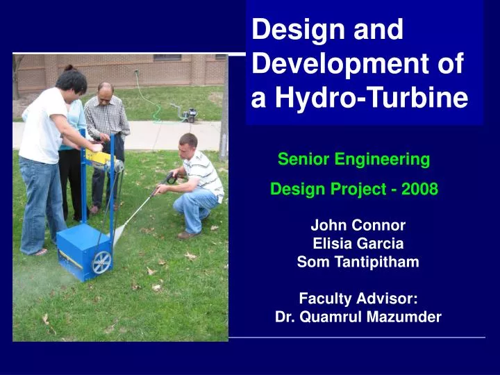
Design and Development of a Hydro-Turbine. Senior Engineering Design Project - 2008. John Connor Elisia Garcia Som Tantipitham Faculty Advisor: Dr. Quamrul Mazumder. Abstract.

E N D
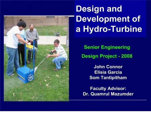
Design and Development of a Hydro-Turbine Senior Engineering Design Project - 2008 John Connor Elisia Garcia Som Tantipitham Faculty Advisor: Dr. Quamrul Mazumder
Abstract • The usage of fossil fuels is slowly being replaced by cleaner and more renewable sources of energy. Since Michigan has varying amounts of sunlight, the use of solar energy would not be practical. With the Flint River located on the campus of the University of Michigan-Flint, hydroelectric energy may be a feasible alternative. Connecting a micro-turbine to a generator and using the natural current of the river can prospectively generate 200 to 300 watts of energy. Funneling the water into the turbine will increase the velocity of the current. With more velocity, more revolutions the turbine will experience. Then, with the goal of 200 to 300 watts desired, the turbine will be equipped with the appropriate number of blades, along with appropriate blade angle. This will ensure that not only the desired energy is produced, but that also that the system is as efficient as possible.
Project Schedule Schedule Performance Index: 102.68%
Efficiency The generator efficiency is directly proportional to the rpm
Assume: ρwater = 62.4 lbm/ft3 Vwater init = 7.5 mph = 11ft/s Vwaterfinal = 7.0 mph = 10.26 ft/s Propeller Diameter = 292 mm = 0 .958 ft Area of Blade = 90 in2= 0.625 ft2 One dimensional Flow Force
FEA • Stress analysis for the turbine support frame • Max stress occurs at the fixed ends • Max stress of about 16000 Pa
FEA • Total deformation of support frame • Max deformation occurs where turbine rest • Max deformation of about 1.7e-8m
FEA • Stress analysis on the turbine • 1400N forced placed on shaft • Max stress 14357Pa
FEA • Total deformation of turbine • 1400N force placed on the shaft • Max deformations is about 0.17m • Cause of large deformations is because sheet metal was used for the blades
Assembly Early Stage of Development: Housing for the Turbine
Assembly First Generator Delivered 300W at 3400rpms
Assembly • Ametek 38 Volt Motor • Can deliver 300W with 600rpms • More compacted and lighter
Assembly Early Stage of Development: Turbine
Changes from Original • Redesigned 10 blades turbine to 8 • Reversed placement of generator on the support to better fit the location • Changed generators
Difficulties • First generator didn’t perform as expected • Water flow of the river was inconsistent • River dried up before final testing could be done
Difficulties River dried up in the location that was going to be used
Plan B Testing • Using a power washer to simulate water flow • Voltage output of 35.5V • Using the performance curve, this is equivalent to 398W of power