Download
1 / 22
230 likes | 287 Views
On handling interrupts. An introduction to the basic issues affecting the design of code that performs servicing of interrupts. Compare-and-branch. We make frequent use of program-loops, such as this one: xor %bx, %bx # initialize array-index again: …

E N D
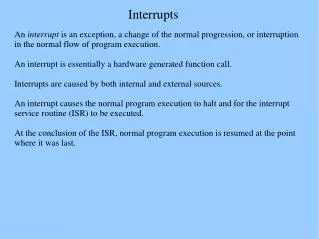
On handling interrupts An introduction to the basic issues affecting the design of code that performs servicing of interrupts
Compare-and-branch • We make frequent use of program-loops, such as this one: xor %bx, %bx # initialize array-index again: … # <body of the loop goes here> … inc %bx # increment array-index cmp $16, %bx # index still below 16? jb again # yes, go through again … # otherwise ‘fall through’
The ‘cmp’ instruction • The instruction ‘cmp’ causes the CPU to perform internally a subtraction-operation • Example: cmp $16, %bx • The value 16 is subtacted from the value in register BX (but without changing BX) • However, the values of bits in the FLAGS register DO get changed, so as to reflect the result of that subtraction-operation!
The FLAGS register Status-flags O F D F I F T F S F Z F 0 A F 0 P F 1 C F Control-flags Legend: ZF = Zero Flag SF = Sign Flag CF = Carry Flag PF = Parity Flag TF = Trap Flag OF = Overflow Flag IF = Interrupt Flag AF = Auxiliary Flag DF = Direction Flag
Effect of ‘cmp $16, %bx’ • When this compare-instruction is executed the first time (while BX = 0x0000), the effect upon the FLAGS value is based on this subtraction: (binary zero) 0000000000000000 (binary 16) - 0000000000100000 ----------------------------------- = 1111111111100000 • Thus SF=1, ZF=0, CF=1 (due to ‘borrow’), etc.
The ‘jb again’ instruction • This conditional-jump instruction examines the setting of the CF-bit (the Carry-Flag) • If CF=1 (i.e., true), then control is transferred to backward, to the instruction at ‘again:’ • If CF=0 (i.e., false), then control continues forward normally (i.e., it “falls through” to the instruction that follows the conditional-jump • The CPU performs its ‘jump’ by adding a signed-integer to the value in register IP
Recall the ‘Fetch-Execute’ cycle Fetch next instruction Advance instruction-pointer Decode fetched instruction Execute decoded instruction INTR ? Interrupt Service Routine no yes
Recall the PC components Central Processing Unit Main Memory system bus I/O device I/O device I/O device I/O device These peripheral I/O components act autonomously (i.e.. independently of whatever the CPU might happen to be doing at any given moment)
Asynchronous interruptions! • So programs can be ‘interrupted’ anytime (i.e., at the end of any fetch-execute cycle) • Maybe even, for example, right here: cmp $16, %bx jb again An interrupt could occur AFTER the cmp-operation has set the FLAGS, but BEFORE the jb-instruction has tested any of those FLAG-bits
Consider the ‘yes’ case Fetch next instruction Advance instruction-pointer Decode fetched instruction Execute decoded instruction INTR ? Interrupt Service Routine no yes The Interrupt Service Routine may do some arithmetical or logical operations that cause FLAGS to be modified – and so invalidate the program’s conditional-jump!
The CPU solves this problem • When an interrupt-request is recognized by the CPU, it automatically ‘saves’ the crucial elements of its program-context • Thereby it can ‘resume’ its main program (after it services the interrupt) with these crucial register-values restored: • The address of the next instruction (CS:IP) • The previous settings of the FLAGS bits
The ‘interruption’ senario Central Processing Unit (CPU) Programmable Interrupt Controller (PIC) Dynamic Random Assess Memory (DRAM) INTR SS SP INTA interrupt handler FLAGS CS IP stack-area main program peripheral device (keyboard, mouse, timer, etc) Interrupt Vector Table
The sequence of actions • Some device issues an interrupt-request • Interrupt Controller forwards it to CPU • CPU saves FLAGS, CS, and IP on stack • CPU issues acknowledgement to PIC • PIC sends Interrupt ID-number to CPU • CPU uses ID-number as index into IVT and loads CS and IP with vector-values
What the ISR works with • The Interrupt Service Routine begins with the its stack setup like this: Saved FLAGS value +4 Saved CS-value +2 Saved IP-value +0 SS:SP (“top” of the stack) room here for the stack to grow downward as needed If the ISR needs to use any of the other CPU registers, it should push their values onto the stack before it modifies them, then pop those saved values back before returning
What does ‘iret’ do? • An Interrupt Service Routine concludes by executing an ‘iret’ instruction -- to resume whatever program had gotten interrupted, and with its FLAGS restored as they were • So what ‘iret’ does is to ‘pop’ the top three word-values off the stack and into the IP, CS, and FLAGS registers, respectively
A role played by the PIC • Before resuming an interrupted program, an interrupt-handler needs to let the PIC know that it has finished servicing the preceding interrupt-request, and that it now is safe to send another request • Otherwise the stack-area might grow too large if more and more new interrupts got sent while old ones were being serviced
The EOI command • Here’s how an interrupt-handler sends an ‘End-Of-Interrupt’ notification to the PIC: • NOTE: It’s pure coincidence that the same number (i.e., ‘$0x20’) is used twice in this code-fragment (but easy to remember it!) • mov $0x20, %al # put EOI command-code in AL • out %al, $0x20 # output AL to port number 0x20
Our demo-program • To illustrate the PC’s interrupt-handling mechanism, we wrote a short program (named ‘tickdemo.s’) that you can study • It has two ‘threads-of-execution’, plus a ‘shared’ variable that both threads use (i.e., one as ‘writer’, the other as ‘reader’) • The main thread stores a new value into the IVT that points to the second thread
A timer-tick will interrupt ‘main’ Our program structure ticks: 0 Our ‘isr’ thread Interrupt vector table = IVT[ 0x08 ] Our ‘main’ thread Vector number 8 will point to our ISR’s entry-point (instead of to a ‘default’ ISR within the ROM-BIOS)
A “critical section” of code • Modifying the timer-tick interrupt-vector is uses a two-step instruction-sequence: • First change the vector’s lo-word (offset) • Then change the vector’s hi-word (segment) • What if an interrupt should occur between those two steps? • We MUST prevent that!! (why?) • So we’ll use the ‘cli’ and ‘sti’ instructions
A thought-experiment • What do you think will happen if we try to reboot the machine (by using ‘int 0x19’) without first restoring Interrupt Vector 8? • You can just comment out the instruction mov %eax, %fs:0x0020 if you want to try out this experiment yourself
In-class exercise • The BIOS startup-code programs the timer so that it issues interrupts at a steady rate of about 18.2 timer-ticks per second • Can you modify our interrupt-handler code so that it only increment the ‘ticks’ counter once-per-second? i.e., like a digital watch • HINT: You may need to add at least one new variable in this program’s data-area