Download
1 / 22
220 likes | 441 Views
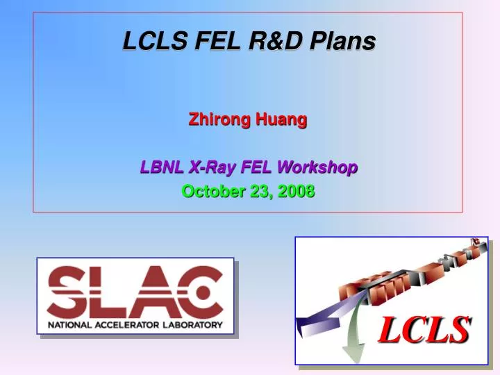
LCLS FEL R&D Plans Zhirong Huang LBNL X-Ray FEL Workshop October 23, 2008. LCLS. R&D in Support of LCLS Present & Future. Brighter electron beams Cathode R&D Short bunch diagnostics. Temporal control of FEL pulses Slotted-spoiler ESASE Seeding laser R&D.

E N D
LCLS FEL R&D PlansZhirong Huang LBNL X-Ray FEL Workshop October 23, 2008 LCLS
R&D in Support of LCLS Present & Future • Brighter electron beams • Cathode R&D • Short bunch diagnostics • Temporal control of FEL pulses • Slotted-spoiler • ESASE • Seeding laser R&D • Extending LCLS capabilities with new sources • A-line soft x-ray FEL • 2nd undulator in LCLS tunnel
LCLS Cathode Experience • First LCLS Cu cathode was Hydrogen-Ion cleaned – reactive (low QE) • Laser cleaning with RF ON (1 MV/m) damaged the cathode surface… The ‘L’ – laser cleaning with RF (1MV/m) The Grid – laser cleaning w/o RF e-beam image Courtesy A. Brachmann
Time-sliced x-Emittance at 20pC Theoretical limit = 0.5 mm/mm (D. Dowell) Towards Smaller Cathode Emittance • New cathode not H-Ion cleaned and QE is immediately high (~510-5), Thermal emittance greatly improved! • Improve our understanding of cathode surface • Try single-crystal Cu (better than polycrystals and closer to theoretical limit?)
Higher-brightness electron sources • Injector Test Facility • A better gun would immediately improve LCLS performance • Dramatically reduces risks on LCLS upgrades to harder x-rays E. Colby, D. Dowell et. al., SLAC-TN-07-005
x S-band deflectors built at SLAC in 1960’s – now 2 installed in LCLS X-Band Deflector for Short Bunch Diagnostics • X-band deflector improves temporal resolution by 4!Plans in place to design an x-band deflector after LCLS undulator to monitor bunch length on shot-by-shot basis(f = 11 GHz. V0 = 33 MV, sz ~ 5 fs)
R&D in Support of LCLS Present & Future • Brighter electron beams • Cathode R&D • Short bunch diagnostics • Temporal control of FEL pulses • Slotted-spoiler • ESASE • Seeding laser R&D • Extending LCLS capabilities with new sources • A-line soft x-ray FEL • 2nd undulator in LCLS tunnel
1 mm emittance 6 mm emittance 1 mm emittance Slotted-spoiler for x-ray pulse length control LCLS BC2 15-mm Be foil P. Emma et al. PRL, 2004
0.25 mm 0-6 mm 10 0-150 fs 5 Power (GW) 2 fs 0 time (fs) 2-Pulse Production with 2 slots 1.5 Å simulation z 60 m 2 fs fwhm pulses not coherent • X-ray pulse length adjustable by slit width • 400 as single x-ray spike possible by changing e-beam configuration
15-25 kA Peak current, I/I0 z /lL One optical cycle ESASE Modulation Acceleration Bunching 30-100 fs pulse lL~0.8 to 2.2mm E ~ 4.5 GeV E ~ 14 GeV A. Zholents, PRST-AB, 2005
Chicane buncher R56 = 0.3-0.8 mm wiggler ~3 m 10-period 10-GW laser L = 0.8-2.2 m ESASE in the LCLS 4.54 GeV z 0.02 mm rf gun rf gun Linac-1 L 9 m rf -25° Linac-2 L 330 m rf -41° Linac-3 L 550 m rf -10° 13.6 GeV new Linac-0 L 6 m Linac-1 BC1 Linac-2 BC2 Linac-3 Linac-0 undulator L 130 m undulator L 130 m X X …existing linac …existing linac BC1 R5639 mm BC2 R5625 mm DL2 Laser Heater Laser Heater DL2 R560 DL1 R56-6 mm SLAC linac tunnel undulator hall New elements
ESASE single spike selection • Two ten-cycle lasers (second laser tunable wavelength with OPA) • Tapered undulator to compensate LSC and enhance contrast E (MeV) P(GW) Ding, Huang, Ratner, Bucksbaum, Merdji, FEL2008
Ti:sapphire Master Oscillator 5 fs, 68 MHz, RF Synchronized DFG 2 mm Pulse Stretcher Ti:sapphire Amplifier 3.5 mJ, 1 kHz, 35 fs Wavelength Selection Kr Cell • Goals • Energy: < 1 mJ • Pulsewidth: ~25 fs • ~ 2.5 optical cycles • Wavelength: 2.0 mm tunable • High Harmonic Generation • ESASE • Laser Engineering for Facilities OPCPA 2 mm Pulse Compressor OPCPA Pump Laser 1053 nm, 40 ps Laser R&D for ESASE and HHG seeding Courtesy G. Hays, W. White
R&D in Support of LCLS Present & Future • Brighter electron beams • Cathode R&D • Short bunch diagnostics • Temporal control of FEL pulses • Slotted-spoiler • ESASE • Seeding laser R&D • Extending LCLS capabilities with new sources • A-line soft x-ray FEL • 2nd undulator in LCLS tunnel
A-Line ESA Soft X-raysA First Reconnaissance R. Arnold, J. Arthur, P. Emma, R. Erickson, T. Fieguth, C. Hast, J. Hastings, M. Hogan, Z. Huang, Y. Nosochkov, D. Walz, M. Woodley, M. Woods • Use 14 GeV LCLS beam (4 GeV possible too) • Steal LCLS pulses into A-Line at BSY (no bypass line yet) • Allows simultaneous hard & soft x-rays (60 Hz each + ?) • Wavelength range: 1.5 - 5.0 nm (little LCLS overlap) • Helical undulator? (shorter, but high technical challenge) • Optical klystron enhancement? (shorter & very effective at 14 GeV!) • Polarization control and/or 2nd-harmonic afterburner? (need space) • Include wide-band spontaneous undulator?
A-Line ESA B-Line LCLS A-line ESA Layout Draft 80 m
Helical Undulator AND Optical Klystrons? E = 14 GeV lr = 1.5 nm gex,y= 2.0 mm Ipk = 3 kA sE/E = 0.01% lu = 8 cm K = 7-13.4 b = 10 m gap 12 mm
Polarization Control by Crossed Undulator • Horizontal + vertical undulators or two helical undulators • Polarization controlled by phase shifter, fast switch possible with pulsed dipoles at ~100 Hz -π/2 π/4 -π/4 0 Ex + Ey Phase shifter π 5π/4 π/2 π/2 • Studies show that equal power in x & y requires L2 = 1.3LG • Over 80% polarization is expected at SASE saturation • Second undulator can be adjusted as a second-harmonic afterburner if needed K.-J. Kim, NIMA 2000 Y. Ding & Z. Huang,PRST-AB 2008
RF gun-2 L0 RF gun-2 2nd Undulator in LCLS Tunnel (LCLS-II?)(3-28 GeV, 0.4-30 Å) 3-14 GeV undulator RF gun-1 3-14 GeV bypass line L0 undulator X X L1 BC1 L2 BC2 L3 L1 BC1 L2 BC2 L3 14-28 GeV FACET wall existing und-hall • Pump-probe capabilities with soft-hard, hard-hard x-ray FELs • THz pump, soft/hard x-ray probe J. Hastings, P. Emma, …
28 GeV hard x-ray FEL • Use the same LCLS undulator, we may reach ~0.4 Å (30 keV photon) by doubling LCLS energy • Take emittancege = 0.5 or 0.8 m, Ipk = 6 kA, <>= 35 m GENESIS simulations including energy spread diffusion due to ISR • Required beam brightness may already have been met by measured LCLS injector performance at low charge
Linac Coherent Light Source at SLAC Use more LINAC – a second undulator in the existing undulator hall 28 GeV Operations wavelengths down to 0.4 Å Options for pump – probe Hard x-ray – Hard x-ray Soft x-ray – Hard x-ray THz – soft/hard x-ray Soft x-rays in ESA 1- 5 nm Variable polarization High peak power
Thanks for your attention! Special thanks to: A. Brachmann, Y. Ding, D. Dowell, P. Emma, J. Frisch,J. Galayda, J. Hastings, H. Loos, C. Pellegrini, W. White, J. Wu ……