Download
1 / 32
360 likes | 607 Views
~There are many instances when it is much more convenient to work in terms of the number of moles (N A , N B ) or molar flow rate (F A , F B , etc.) rather than conversion. ~Membrane reactors and multiple reactions taking place in the gas phase are two such

E N D
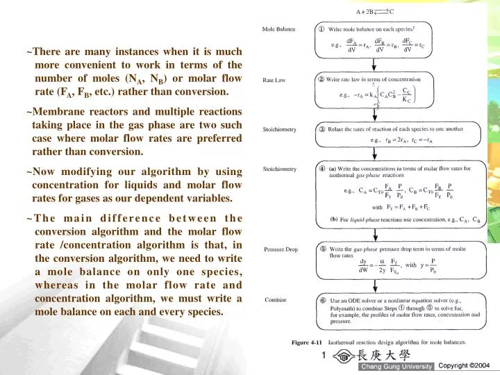
~There are many instances when it is much more convenient to work in terms of the number of moles (NA, NB) or molar flow rate (FA, FB, etc.) rather than conversion. ~Membrane reactors and multiple reactions taking place in the gas phase are two such case where molar flow rates are preferred rather than conversion. ~Now modifying our algorithm by using concentration for liquids and molar flow rates for gases as our dependent variables. ~The main difference between the conversion algorithm and the molar flow rate /concentration algorithm is that, in the conversion algorithm, we need to write a mole balance on only one species, whereas in the molar flow rate and concentration algorithm, we must write a mole balance on each and every species.
Mole Balances on CSTRs, PFRs, PBRs, and Batch Reactors Liquid Phase For liquid-phase reactions in which there is no volume change, concentration is the preferred variable. Consider a general reaction We have to only to specify the parameter values for the system (CA0, v0, etc) and for the rate law parameters (e.g., kA, , ) to solve the coupled ordinary differential equations for either PFR, PBR, or batch reactors or to solve the coupled algebraic equation for a CSTR.
Gas Phase Rate law Mole balance Stoichiometry Pressure drop Total flow rate
Microreactors ~Microreactors are emerging as new technology in CRE. Microreactor are characterized by their high surface area-to-volume ratios in their microstructured regions that contain tubes or channels. ~A typical channel width might be 100 m with a length of 20000 m (2 cm). The resulting high surface area-to-volume ratio (ca. 10000 m2/m3) reduces or even eliminates heat and mass transfer resistances often found in larger reactors. ~Consequently, surface catalyzed reactions can be greatly facilitated, hot spots in highly exothermic reactions can be eliminated, and in many case highly exothermic reactions can be carried out isothermally. ~These features provide the opportunity for microreactors to be used to study the intrinsic kinetics of reactions. ~Another advantage of microreactor is their use in the production of toxic or explosive intermediates where a leak of microexplosion for a single unit will do minimal damage because of the small quantities of material involved. ~Other advantages include shorter residence times and narrow residence time distributions.
Figure 4-12 shows (a) a microreactor with heat exchanger and (b) a microplant with reactor, valves, and mixers. Heat, Q, is added or taken away by the fluid flowing perpendicular to the reaction channels shown in Figure 4-12(a). Production in microreactor systems can be increased simply by adding more units in parallel. For example, the catalyzed reaction required only 32 microreaction systems in parallel to produce 2000 tons/yr of acetate In modeling microreactors, we will assume they are either in plug flow for which the mole balance is or in laminar flow, in which case we will use the segregation model.
Example 4-7 The gas-phase reaction 2NOCl2NO+Cl2 is carried out at 425C and 1641 kPa (16.2 atm). Pure NOCl is to be fed, and the reaction follows an elementary rate law. It is desired to produce 20 tons of NO per year in a microreactor system using a bank of ten microreactors in parallel. Each microreactor has 100 channels with each channel 0.2 mm square and 250 mm in length. Plot the molar flow rates as a function of volume down the length of the reactor. The volume of each channel is 10-5 dm3. To produce 20 tons per year of NO at 85% conversion would require a feed rate of 0.0226 mol/s of NOCl per channel. The rate constant is
Solution V=? Mole balance Rate law Stoichiometry: Gas phase with T=T0 and P=P0, then v=v0FT/FT0
combining evaluating using polymath or another ODE solver
Membrane Reactors ~Membrane reactors can be used to increase conversion when the reactions is thermodynamically limited as well as to increase the selectivity when multiple reactions are occurring. ~Thermodynamically limited reactions are reactions where the equilibrium lies far to the left (i.e. reactant side) and there is little conversion. ~If the reaction is exothermic, increasing the temperature will only drive the reaction further to the left, and decreasing the temperature will result in a reaction rate so slow that there is very little conversion. ~If the reaction is endothermic, increasing the temperature will move the reaction to the right to favor a higher conversion; however, for many reactions these higher temperatures cause the catalyst to become deactivated.
~The term membrane reactor describes a number of different types of reactor configuration that contain a membrane. ~The membrane can either provide a barrier to certain components while being permeable to others, prevent certain component such as particulates from contacting catalyst, or contain reactive sites and be a catalyst in itself. ~Like reactive distillation, the membrane reactor is another technique for driving reversible reactions to the right toward completion in order to achieve very high conversions. ~These high conversions can be achieved by having one of the reaction products diffuse out of a semipermeable membrane surrounding the reacting mixture. As a result, the reverse reaction will not be able to take place, and the reaction will continue to proceed to the right toward completion.
Figure 4-13 shows two of the main type of catalytic membrane reactors. The reactor in Figure 4-13(b) is called an inert membrane reactor with catalyst pellets on feed side (IMRCF). Here the membrane is inert and serves as a barrier to the reactants and some of the products. Figure 4-13(C) is a catalytic membrane reactor (CMR). The catalyst is deposited directly on the membrane, and only specific reaction products are able to exit the permeate side. For example, in the reversible reaction the hydrogen molecule is small enough to diffuse through the small pores of the membrane while C6H12 and C6H6 cannot. Consequently, the reaction continues to proceed to the right even for a small value of the equilibrium constant.
Hydrogen, species B, flows out through the sides of the reactor as it flows down the reactor with the other products, which cannot leave until they exit the reactor. Choosing the reactor volume rather than catalyst weight as a independent variable Balance on A and C in the catalytic bed: Balance on B in the catalytic bed: RB is the molar rate of B leaving through the sides the reactor per unit volume of reactor (mol/dm3/s)
The rate of transport B out through the membrane RB is the product of the molar flux of B, WB, and a, the surface area, per unit volume of reactor kC’ is the overall mass transfer coefficient in m/s and CBS is the concentration of B in the sweep gas channel (mol/dm3). The overall mass transfer coefficient accounts for all resistances to transport: the tube side resistance of the membrane, the membrane itself, and on the shell (sweep gas) side resistance. The overall mass transfer coefficient can be a function of the membrane and fluid properties, the fluid velocity, and the tube diameters. The membrane surface area per unit volume of reactor is
Example 4-8 According to The Department of Energy (DOE), an energy saving of 10 trillion BTU per year could result from the use of catalytic membrane reactors as replacements for conventional reactors for dehydrogenation reactions such as the dehydrogenation of ethylbenzene to styrene: and of butane to butene: C4H10C4H8+H2 The dehydrogenation of propane is another reaction that has proven successful with a membrane reactor: C3H8C3H6+H2 All the preceding dehydrogenation reactions above can be represented symbolically as AB+C And will take place on the catalyst of an IMRCF. The equilibrium constant for this reaction is quite small at 227C (e.g., KC = 0.05 mol/dm3). The membrane is permeable to B (e.g., H2) but not to A and C. Pure gaseous A enters the reactor at 8.2 atm and 227C at a rate of 10 mol/min. We will take the rate of diffusion of B out of the reactor per unit volume of reactor, RB, to be proportional to the concentration of B (i.e., RB = kCCB). (a)Perform differential mole balances on A, B, and C to arrive at a set of coupled differential equations to solve. (b)Plot the molar flow rate of each species as a function of space time. (c)Calculate the conversion.
Addition information: Even though this reaction is a gas-solid catalytic reaction, we will use the bulk catalyst density in order to write our balances in terms of reaction volume rather than catalyst weight (-rA = -rA’b). For the bulk catalyst density of b = 1.5g/cm3 and a 2-cm inside diameter of the tube containing the catalyst pellets, the specific reaction rate, k, and the transport coefficient, kC, are k = 0.7 min-1 and kC = 0.2 min-1, respectively. Solution (a) Mole balance RB is the molar flow of B out through the membrane per unit volume of reactor Rate law Transport out of the reactor kC is a transport coefficient (constant).
evaluating (b) (c) ?
Use of Membrane Reactors to Enhance Selectivity In addition to species leaving the membrane reactor, species can also be fed to the reactor through the membrane. For example, for the reaction A could be fed only to the entrance, and B could be fed only through the membrane as shown here. This arrangement is often used to improve selectivity when multiple reactions take place. Here B is usually fed uniformly through the membrane along the length of the reactor. The balance on B is where RB=FB0/Vt, with FB0 the molar feed rate of B through sides and Vt the total reactor volume.
Unsteady-State Operation of Stirred Reactors ~The startup of a CSTR is examined to determined the time necessary to reach steady-state operation (see Figure 4-14(a)), and then semibatch reactor are discussed. ~In each of these case, we are interested in predicting the concentration and conversion as a function of time. ~Close-form analytical solutions to the differential equations arising from the mole balance of these reaction types can be obtained only for zero- and first-order reactions. ODE solvers must be used for other reaction orders.
One of the reactants in the reaction A+BC+D (e.g., B) is slowly fed to a reactor containing the other reactant (e.g., A), which has already been charged to a reactor such as that shown in Figure 4-14(b). This type of reactor is generally used when unwanted side reactions occur at high concentration of B or when the reaction is highly exothermic. In some reactions, the reactant B is a gas and is bubbled continuously through liquid reactant A. Examples of reactions used in this type of semibatch reactor operation include ammonolysis, chlorination, and hydrolysis.
The other type of semibatch reactor is reactive distillation and is shown schematically in Figure 4-14(c). Here reactants A and B are charged simultaneously and one of the product is vaporized and withdrawn continuously. Removal of one of the products in this manner (e.g., C) shifts the equilibrium toward the right, increasing the final conversion above that which would be achieved had C not been removed. In addition, removal of one of the products further concentrate the reactant, thereby producing an increase rate of reaction and decreased processing time. Examples of reactions carried out in this type of reactor include acetylation reactions and esterification reactions in which water is removed.
Startup of a CSTR Consider the case when the reactor is well mixed and as a result there are no spatial variations in rA liquid phase (v=v0) reactions with constant overflow (V=V0) Letting ts be the time necessary to reach 99% of the steady-sate concentration, CAS: slow reaction rapid reaction
Semibatch Reactors One of the best reasons to use semibatch reactors is to enhance selectivity in liquid-phase reactions. For example, consider the following two simultaneous reactions. One reaction produces the desired product D The other produces an undesired product U The instantaneous selectivity SD/U is the ratio of the relative rates guiding us how to produce the most of our desired product and least of our undesired product We can increase the formation of D and decrease the formation of U by keeping the concentration of A high and the concentration of B low. This result can be achieved through the use of the semibatch reactor, which is charged with pure A and to which B is fed slowly to A in the vat.
Writing the Semibatch Reactor Equations in Terms of Concentrations Of the two type of semibatch reactors, we focus attention primarily on the one with constant molar feed. A schematic diagram of this semibatch reactor is shown in Figure 4-15. Consider the elementary liquid-phase reaction in which reactant B is slowly added to a well-mixed vat containing reactant A mole balance on species A mole balance on species B
Since the reactor is being filled, the volume, V, varies with time. The reactor volume at any time t can be found from an overall mass balance of all species: Constant-density system At time t = 0, the initial concentration of B in the vat is zero, CBi = 0. The concentration of B in the feed is CB0. If the reaction order is other than zero- or first-order or if the reaction is nonisothermal, we must use numerical techniques to determine the conversion as a function of time.
Example 4-9 The production of methyl bromide is an irreversible liquid-phase reaction that follows an elementary law. The reaction CNBr+CH3NH2CH3Br+NCNH2 is carried out isothermally in a semibatch reactor. An aqueous solution of methyl amine (B) at a concentration of 0.025 mol/dm3 is to fed at rate of 0.05 dm3/s to an aqueous solution of bromine cyanide (A) contained in a glass-lined reactor. The initial volume of fluid in a vat is to be 5 dm3 with a bromine cyanide concentration of 0.05 mol/dm3. The specific reaction rate constant is k = 2.2 dm3/smol Solve for the concentration of bromine cyanide and methyl bromide and the rate of reaction as a function of time. Solution
Why ? X vs. t ?
Writing the Semibatch Reactor Equations in Terms of Conversion Consider the reaction in which B is fed to a vat containing only A initially. The reaction is first-order in A and first-order in B. for species A for species B constant molar feed rate no B initially in the vat
for species C and D rate law solved numerically to determine the conversion as a function of time
Xe X The maximum attainable conversion (i.e., the equilibrium conversion) will change as the reaction proceeds because more reactant is continually added to the reactor. This addition shifts the equilibrium continually to the right toward more product. t
Reactive distillation is used with thermodynamically limited reversible liquid-phase reactions and is particularly attractive when one of the products has a lower boiling point than the reactants. For reversible reactions of this type, the equilibrium lies far to the left, and little product is formed. However, if one or more of the product (e.g., D) is removed by vaporization, as shown in Figure 4-16, the reaction will continue toward completion. The equilibrium constant is removed, and more product will be formed.
Closure ~This section presents the heart of chemical reaction engineering for isothermal reactors. After completing this section, the student should be able to apply the algorithm building blocks (mole balance, rate law, stoichiometry, combine, evaluate) to any of the reactors discussed in this section: batch reactor, CSTR, PFR, PBR, membrane reactor, and semibatch reactor. ~The student should be able to account for pressure drop and describe the effects of the system variable such as particle size on the conversion and explain why there is an optimum in the conversion when the catalyst particle size is varied. ~The student should be able to use either conversion or concentration and molar flow rates to solve chemical reaction engineering problems.