Download
1 / 41
1.02k likes | 1.95k Views
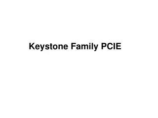
COM509 Computer Systems. Lecture 2. Chipset and PCIe. Prof. Taeweon Suh Computer Science Education Korea University. x86-based Computer System. CPU. Main Memory (DDR2). FSB (Front-Side Bus). North Bridge. Graphics card. South Bridge. Hard disk. BIOS ROM. USB. PCIe card.

E N D
COM509 Computer Systems Lecture 2. Chipset and PCIe Prof. Taeweon Suh Computer Science Education Korea University
x86-based Computer System CPU Main Memory (DDR2) FSB (Front-Side Bus) North Bridge Graphics card South Bridge Hard disk BIOS ROM USB PCIe card
Chipsets • Chipsets include MCH and ICH in the x86-based system • There are PCIe devices inside the MCH and the ICH • Backbone of MCH and ICH is based on PCI express • Q35 (North Bridge) • Device 0 : Function 0 • DRAM Controller Registers • Device 1 : Function 0 • PCIe Registers associated with x16 root port • Device 2 : Function 0, 1 • Integrated Graphics Devices Registers • Device 3 : Function 0, 1, 2, 3 • Intel Management Engine (ME) subsystem registers
Chipsets • ICH9 (South Bridge) • D30:F0 • PCI-to-PCI Bridge Register • D31:F0 • LPC (Low Pin Count) Interface Bridge Registers • D31:F2 • SATA (Serial ATA) Controller Registers • D31:F3 • SMBus Controller Registers • ….
PCI Express • 3rd generation high-performance I/O bus • Used to interconnect peripheral devices • Point-to-point connection as opposed to bus • PCIe interconnect consists of either a x1, x2, x4, x8, x12, x16 or x32 point-to-point link • if you have x16 link, there are 64 physical lines (16 * 2 (both directions) * 2 (differential signaling)) • 1st generation • ISA, EISA, VESA and Micro Channel buses • 2nd generation • PCI, PCI-X, and AGP
PCIe-based System Topology • Root Complex • Denote the root of I/O hierarchy that connects the CPU/memory subsystem to the I/O • May support one or more PCIe ports as shown • Endpoint • devices other than root complex and switches that are requesters or completers of PCIe transactions Souce: PCIe specification 2.0
PCIe Example Topology • Switch • Can be thought of as consisting of 2 or more logical PCI-to-PCI bridges • One port of a switch pointing in the direction of the root complex is an upstream port • All other ports pointing away from the root complex are downstream ports Souce: PCIe specification 2.0
PCIe Address Space • PCIe supports the same address spaces as PCI • Memory space • IO space • Configuration space • PCIe provides a 4KB space per a function as opposed to 256B in PCI • PCIe support up to 256 buses, 32 devices, and 8 functions
PCIe Configuration Registers • Vendor ID • Identify the manufacturer of the function • The value is assigned by a central authority (PCI SIG) that controls issuance of the numbers • Device ID • Assigned by the function manufacturer • Identify the type of the function
PCIe Configuration Registers • Class code
How to Access Configuration Registers? • In x86-based platform, there are 2 ways to access configuration registers • I/O transaction with 0xcf8 and 0xcfc • PCI compatible configuration mechanism • 0xcf8 and 0xcfc are IO port addresses implemented within root complex • It means you have to use “in” or “out” instructions in x86 • 0xcf8: Configuration address port • 0xcfc: Configuration data port
How to Access Configuration Registers? • MMIO (Memory-Mapped IO) transaction • Each function’s 4KB config. space starts at a 4KB-aligned address with the 256MB memory space set aside as configuration space • For example, you can use “mov” instruction in x86 to access the config. space
PCIe Transaction Routing TLP: Transaction Layer Packet
PCIe Enumeration • At power up time, the configuration software only knows of the existence of bus 0 • Bus 0 is the bus that resides on the downstream side of the Host/PCI bridge • The configuration S/W does not even know what devices reside on bus 0 • So… how does the system discover the various buses, devices, and functions on the computer system? • Answer: Via the enumeration process • BIOS is doing the enumeration
PCIe Enumeration Process • ………