Download

1 / 42
430 likes | 620 Views
PXL-500 Installation Site Preparation. Purpose of Site Preparation. Quick and efficient site setup Ensure the site has all necessary facilities Ensure the site has all necessary materials Plan for placement of equipment into maintainable locations Ensure proper site cabling

E N D
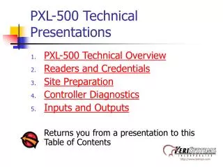
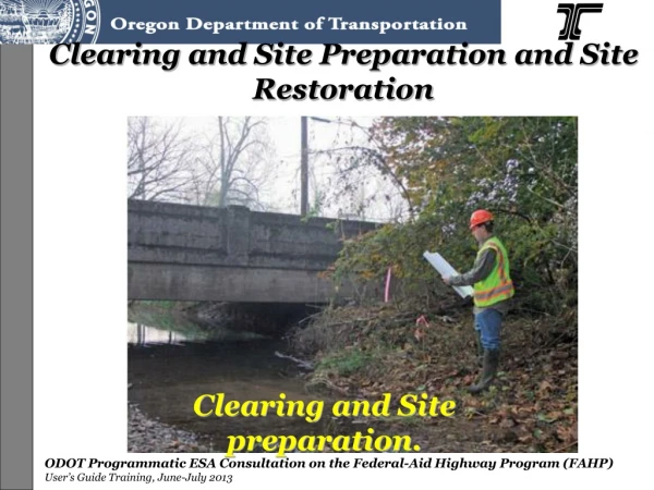
PXL-500 Installation Site Preparation
Purpose of Site Preparation • Quick and efficient site setup • Ensure the site has all necessary facilities • Ensure the site has all necessary materials • Plan for placement of equipment into maintainable locations • Ensure proper site cabling • Provide safety and equipment protection
Earth Ground EMI Transients Utility Requirements Power Outlets Analog Phone Lines Controller Mounting Central versus Distributed Master Controller Reader Mounting Enrollment Reader Cabling We’ll be Covering . . .
Earth Ground • Required by building codes for safety • Provides the best controller operating conditions • A poor earth ground degrades system performance
Earth Ground versus EMI • Reduces susceptibility to Electromagnetic Interference (EMI): • Brings all electrically neutral lines to the earth’s surface potential (zero potential) • Provides a return path to ground for electrical interference
Electromagnetic Interference (EMI) • EMI is radiated electromagnetic energy from one electrical device that may affect the operation of other electrical devices • Data lines are particularly susceptible
Common EMI Sources • Power Supplies • Use only commercially built, regulated power supplies • Computers/Monitors • Placing a computer monitor near a proximity reader can drastically affect the reader’s read range • Power Lines • Power lines radiate EMI
Common EMI Sources • Electric motors • Power transformers • Air conditioning and heating units • Cable routing • Separating controller power lines from data lines provides an extra level of EMI protection
Earth Ground versus Transients • Reduces susceptibility to power line transients (quick, brief surges in power): • Helps protect the controller from electrical transients such as power surges and lightning strikes
Transients • Electrical surges or spikes conducted through power, input, or output lines that can easily damage electrical components • Commonly generated when electric devices are turned on or off • Door locks • Motors • Floodlights
Suppression Using Transorbs • Protects against quick surges • Acts like a bi-polar diode, passes voltage up to a certain point and then clamps off, preventing higher voltages from passing through
Suppression Using MOVs • Metal-Oxide Varistor • Protects relay contacts • Acts like a capacitor, absorbs the initial surge and releases it slowly into the system
Suppression Using Isolation Relays • Protects against major surges by separating the path with transients from the path connected to the controller
An Earth Ground Increases Safety • A poor earth ground is a safety issue, introducing the possibility of electric shock
Earth Ground Sources • Possible earth ground sources: • copper shrouded ground rod • metal, cold water pipe • steel building framing (if framing is embedded into the earth) • electrical system ground (at the breaker/fuse box) • telephone system ground
Utility Requirements • Power Outlets • Analog Phone Lines
Utility Requirements • Power Outlets • Must have one for each power supply supporting controllers, electric door locks, and all other accessories • Must be easily accessible • Must be grounded
Utility Requirements • Analog Phone Lines • Two are needed if communication between access control network and host computer is done via modems
Controller Mounting • Review site requirements to determine where controllers should be mounted • Costs (installation and maintenance)versus controller security • There are two types of controller mounting to consider • Central Mounting • Distributed Mounting
Central Controller Mounting • All controllers mounted in one location (i.e. a facilities closet, telco room, server room)
Central Controller Mounting • PROs • Easier controller maintenance • Can provide greater security • Shorter cable runs for the controller network and for unit power • Units can share a larger power supply
Central Controller Mounting • CONs • Longer cable runs to support readers, inputs, outputs, door lock, etc. • May use much more cable than Distributed Mounting
Distributed Controller Mounting • Places a controller by each door
Distributed Controller Mounting • PROs • Controller/door proximity • Easier to troubleshoot • Shorter cable runs to support readers, inputs, outputs, door lock, etc. • May use less cable than Central Mounting
Distributed Controller Mounting • CONs • Longer cable run for the controller network • Needs individual power supplies for each controller • Harder to maintain controllers • Harder to secure controllers
Master Controller Location • Consider locating the master controller in a more easily accessible place: • Advantages • easier to perform diagnostics (particularly if an LCD-1 is installed on the controller) • easier PC to network access • enrollment reader access for presentation enrollment and for lost card identification
Controller Mounting • Mount controllers in environmentally suitable locations • For indoor controller installations - mount enclosures on any type of solid wall surface • For outdoor controller installations - controllers must be in water tight, weatherproof enclosures
Controller Mounting • Easiest way to mark drilling holes for the enclosure is to have an associate hold the enclosure in place and mark the drilling holes with a pencil
Controller Mounting • Individual controller panel PCBs can be mounted the same way, but mounting must be done using standoffs to provide PCB/wall clearance
Controller Mounting • Note the cable routes to the controller and remove the enclosure knockouts that best accommodate the cable routes
Enrollment Reader • The “A” reader on the Master Controller • Used for presentation enrollment • Not needed if all cards are block enrolled
Enrollment Reader • Place the reader near the host computer for ease of presentation enrollment • But not too close because EMI from the computer will affect the reader
Enrollment Reader • Can also be used for access control if desired, but: • Proximity to host computer may be an issue; starting the enrollment process, then running to the reader to complete the enrollment • Access requests are ignored during presentation enrollment which may confuse users • The Show Face and ID Card functions also use the Enrollment Reader
Reader Mounting • Users need clear access to readers • It should not be mounted in a way that affects traffic paths • Be aware of Americans with Disabilities Act (ADA) requirements that can affect where you place the reader
Cabling • You must use proper cabling for best operating conditions • Shielded to minimize EMI • Proper gauge to minimize voltage drop over long run lengths • Routed in a way that allows for maintenance
Cable Requirements • RS-232 - Controller to Host Computer • Three conductor, shielded, stranded, AWG 24 (or larger gauge) • 50 feet maximum length (per RS-232 specification)
Cable Requirements • RS-485 – Controller to Controller Network • Two conductor, shielded, stranded, twisted pair, AWG 24 (or larger gauge) • 16,000 feet maximum network length when installed using Keri networking guidelines
Cable Requirements • Power • Two conductor, stranded, AWG 18 (or larger gauge) • 200 feet maximum length • Watch for a drop in voltage over long power runs due to resistance in the cable length • The controller must have 12 VDC at the controller for proper operation
Cable Requirements • Earth Ground • Single conductor, AWG 18 (or larger gauge)
Cable Requirements • Inputs and Outputs • Two conductor, stranded, AWG 22 (or larger gauge) • The lock output relay may require a heavier gauge of wire depending upon the current demands of the lock and the length of the wiring run
When Routing Cable • DO • Route cables in accessible areas for easy maintenance • Use transient suppression across electric devices attached to the PXL-500 or SB-593 output relays (at the device itself) • Use an isolation relay if connecting to a parking gate, turnstile, elevator car, or any application using a large electric motor (at the device itself)
When Routing Cable • DO NOT • Route cables near EMI sources • Cables can act as antennas, receiving EMI that affects controller operation • EMI sources include power lines (including air conditioning or heating lines), door lock and power supply lines, network data lines • Stretch cables • Route cables over sharp edges or hot objects