Download
1 / 49
510 likes | 640 Views
Radio Propagation in Hallways and Streets for UHF Communications. Dana Porrat Advisor: Professor Donald Cox. Outline. Propagation in cellular systems The over-moded waveguide model Comparison to measurements Applications of the model. Propagation Models.

E N D
Radio Propagation in Hallways and Streetsfor UHF Communications Dana Porrat Advisor: Professor Donald Cox
Outline • Propagation in cellular systems • The over-moded waveguide model • Comparison to measurements • Applications of the model
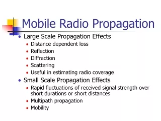
Propagation Models • Ray tracing – requires a lot of detail and computation (Bell Labs, Bertoni, Rappaport) • Power laws – give a very general picture, weakly linked to geometry • Usage: • Power levels – Coverage and Interference • Other properties of link
Guided Radiation • Street canyon effects in cities have been measured many times • Guiding by indoor hallways – shown by measurements
Motivation • Insight into the propagation mechanism in hallways and streets • Average predictions based on geometry, with reasonable detail and low complexity
Outline • The multi-moded waveguide model • Comparison to measurements • Applications of the model
Key Features • The wavelength at 1 GHz is 30 cm – much smaller than hallways and streets • Multi-moded waveguide • The walls are not smooth • Mode coupling
The Smooth Waveguide x d 2nd 1st z 8th -d
The TEM mode • Field components: Hy and Ex • Present for 2D smooth waveguide • Not present for 3D rough waveguide
D Correlation Length s Perturbation Variance The Rough Waveguide x d x=h(z) z x=f(z) -d Dielectric Waveguide: D. Marcuse, 1970’s
Rough Walls Expansion in terms of the waveguide modes are the amplitudes of the modes
The Perturbation Approach • The wave equation for the smooth guide: • For the rough guide: • After manipulation:
The Perturbation Solution hold the spectrum of f(z), h(z)
The Coupled Modes The coupling coefficients among modes:
Assumptions • Air filled waveguide, homogeneous material, rough boundaries • Two dimensional model • Small roughness, compared to l • Coupling coefficients , has a Gaussian correlation with s, D • Coupling between TE-TM modes behaves as single polarization coupling
Coupled Power Equations Coupling from the nth mode into other modes Loss of the nth mode Coupling from other modes into the nth mode
Power Coupling Coefficients The coupling coefficients:
Solution of the Coupled Eq Solution:
The Steady State Solution The steady state distribution has most of power in lowest order TE mode P [dB] Mode (n)
P z n n Dynamic Solutions • Development along hallway / street • Initial conditions: • Small antenna • Junction
Junctions Side Hallway Low order modes of the main hallway couple into high order modes of the side hallway Main Hallway
Floor and Ceiling • Full 3D model is very complicated • Simplification: smooth perfectly conducting floor and ceiling • Vertical and horizontal are independent
The Packard Basement 4 2 1 3 Tx Power [dB] 5 y [m] 6 x [m]
Hallway 1 Power Simulation parameters: e = 3, s = 0.085 S/m s2 = 0.2 m2, D = 2 m dTE initial conditions Power [dB] y [m]
The Packard Basement 4 2 1 3 Tx Power [dB] 5 y [m] 6 x [m]
Power Across Hallway 1 4.4 m Power [dB] 12 m x [m]
The Packard Basement 4 2 1 3 Tx Power [dB] 5 y [m] 6 x [m]
Hallway 6 Power Simulation parameters: e = 3, s = 0.085 S/m s2 = 0.2 m2, D = 2 m Uniform initial conditions Power [dB] y [m]
The Packard Basement 4 2 1 3 Tx Power [dB] 5 y [m] 6 x [m]
Hallway 6 and Rooms Power [dB] y [m] Simulation parameters: e = 3, s = 0.085 S/m s2 = 0.2 m2, D = 2 m Uniform initial conditions
The Packard Basement 4 2 1 3 Tx Power [dB] 5 y [m] 6 x [m]
Hallway 5 and Rooms Power [dB] x [m] Simulation parameters: e = 3, s = 0.085 S/m s2 = 0.2 m2, D = 2 m Uniform initial conditions
Ray Tracing Power [dB] y [m] x [m]
Ray Tracing – Hallway 3 Power [dB] y [m] Simulation parameters: e = 3, s = 0.085 S/m, s2 = 0.2 m2, D = 2 m, Uniform initial conditions
Ottawa Measurements J. Whitteker, 1987
Queen St Measurements Simulation parameters: e = 2.6, s = 0.27 S/m s2 = 0.3 m2, D = 30 m dTE initial conditions Power [dB] Distance along Street [m]
Ottawa Measurements J. Whitteker, 1987
Metcalf St Measurements Simulation parameters: e = 2.4, s = 0.26 S/m, s2 = 0.2 m2, D = 10 m, Uniform initial conditions Power [dB] Distance along Street [m]
Ottawa Measurements J. Whitteker, 1987
Wellington St Measurements Simulation parameters: e = 2.9, s = 0.26 S/m, s2 = 0.2 m2, D = 10 m, Uniform initial conditions Power [dB] Distance along Street [m]
Applications of the Model • Channel Capacity • Delay Spread
Channel Capacity The channel becomes ‘narrow’ at large distances, all the paths become similar Max: 84 bps/Hz 12 x 15 Antennas SNR = 20 dB Capacity [bps/Hz] Distance along Hallway [m] P. Kyritsi, 2001
q n z k The Delay Profile The group velocity v = c cosqn 400 m Power [dB] t[msec]
Contributions • A new waveguide model for hallways and streets with reasonable geometric input. This low complexity model agrees with indoor and outdoor measurements and provides insight to observed phenomena • Demonstration of guiding effects in indoor hallways • A ‘Keyhole’ effect which limits capacity in long hallways and streets • Insight into delay profiles from the multi-moded waveguide model
Publications • D. Porrat and D. C. Cox, UHF Propagation in Indoor Hallways. Submitted to the IEEE Transactions on Wireless Communications, June 2002 • D. Porrat, P. Kyritsi and D. C. Cox, MIMO Capacity in Hallways and Adjacent Rooms. IEEE Globecom, November 17-21, 2002 • D. Porrat and D. C. Cox, Microcell Coverage and Delay Spread Prediction Using Waveguide Theory. URSI General Assembly August 17-24 2002 • D. Porrat and D. C. Cox, Delay Spread in Microcells Analysed with Waveguide Theory. IEEE 55th Vehicular Technology Conference 2002 Spring, May 6-9 • D. Porrat and D. C. Cox, A Waveguide Model for UHF Propagation in Streets. The 11th Virginia Tech/MPRG Symposium on Wireless Personal Communications, June 6-8, 2001
The Over-Moded Waveguide • A single long waveguide • A junction of waveguides