Download
1 / 61
720 likes | 997 Views
Department of Information Engineering University of Pisa. Plenary Talk Advances in Technologies and Architectures for Low-Power and Highly Integrated Ubiquitous Radars. Prof. Sergio Saponara, PhD sergio.saponara@iet.unipi.it. Outline of the Talk.

E N D
Department of Information Engineering University of Pisa. Plenary Talk Advances in Technologies and Architectures for Low-Power and Highly Integrated Ubiquitous Radars Prof. Sergio Saponara, PhD sergio.saponara@iet.unipi.it
Outline of the Talk • Scenarios, applications and requirements for highly-integrated low-power RADAR • RADAR architecture, integration levels, RF/mm-Wave transceivers and ADC • Ubiquitous low-power RADAR case studies: E-health (UWB and Doppler) • Automotive (FMCW) • HW-SW implementing platforms for RADAR DSP • Conclusions
The electronic components market is growing, driven by digital-based highly integrated applications in Si-based tech. addressing societal needs: health, energy, security, safety, transport.. Not only nanoscale CMOS (more Moore) but also (more than Moore) System-in-Package integration of passives, RF & mm-Wave, high voltage, sensors/actuators (MEMS) .. Source: World Semiconductor Trade Statistics
Ubiquitous RADAR applications • Pushed by military applications in II world war with high-power, large size • and long-distance systems, today RADAR can be ubiquitous adopted for: • Safer transport systems in automotive, railway, ships … • Bio-signal detection for health care and elderly/infant monitoring • Info-mobility in urban, airport or port scenarios • Civil engineering, (structural health monitoring, landslide monitoring, ground penetration for detecting pipes, electric lines,….) • Distributed surveillance systems (smart cities, airports, banks, schools) • mm-wave body scanner for security • Environmental monitoring and civil protection • Contactless industrial measurements and in harsh environments • Through-wall target detection
Ubiquitous highly-integrated low-power RADAR RADAR sensing suited to address societal needs (safety, security, health, transport ) ubiquitous adopted for large volume applications? • RADAR sensing advantages w.r.t. other technologies: • operations in all weather and bad light conditions • contactless sensing and no line of sight sensing • non ionizing radiations • ground penetrating capabilities • multi parameter sensing (target detection, distance, speed, angles)
Ubiquitous RADAR design needs • W.r.t. conventional RADARs with large transmitted-power x antenna aperture product, the realization of highly-integrated RADARs with low power consumption, size, weight and cost (using standard technologies) is needed to enable its ubiquitous adoption in large–volume markets • Transmitted Power < 10-15 dBm • Short wavelength for miniaturization (3.9 mm@77 GHz) • Range from < 1m to < 100-200 m • Detection also with low SNR of 10-20 dB • Cross section from tens of cm2 to m2 • DSP techniques to improve performance and solve range-speed ambiguities • Receiver sensitivity down to -100 dBm • Multiple channels may be used for channel diversity gain
Highly integrated ubiquitous RADAR frequency At λ of few mm there is potential for high miniaturization, even the antenna integration 77-81 GHz suited for LRR and SRR, 60 GHz reserved for short range radio Today, good microwave and mm-Waves performance for Si-based technologies
Outline of the Talk • Scenarios and applications for highly-integrated low-power RADAR • RADAR architecture, integration levels, RF/mm-Wave transceivers and ADC • Ubiquitous low-power RADAR case studies: E-health (UWB and Doppler) • Automotive (FMCW) • HW-SW implementing platforms for RADAR DSP • Conclusions
RADAR as mixed analog-digital system DIGITAL DOMAIN Control & Interface (user or networking or mission processor) Data Processing (adaptive threshold, CFAR detection, tracking, classification ..) Signal Processing TX: waveform gener (DDS), DUC RX: DDC, beam-forming, PC-match filter, FFT, .. ANALOG DOMAIN (PA, LNA, LO, MIXER, AGC, FILT, T/R Switch, Phase Shift) ADC DAC • High peak power in integrated systems problematic limit on range, performance gain from DSP rather than power • Integrated high freq T/R (LNA, Mixer, switch, stable LO, ) and embedded I/F and BB DSP platforms (ADC/DAC + MCU + FPGA/DSP)
Low-power RADAR integration levels System-on-Chip (SoC), System-in-Package (SiP) or Single-board RADAR SiP is a more viable solution for RADAR than fully SoC (increased miniaturization entails also increased tech. complexity)
Pro/Con of RADAR integration • Pro of Highly Integrated RADAR • Component assembly minimized reducing cost, increasing reliability & lifetime • Small size, small weight, low power consumption • Increased reproducibility and lower cost for large volume production • Con of Highly Integrated RADAR • IC design has high Non Recurring Costs (CAD tools, foundry cost, design time and team design cost) cost is minimized only for large volume production • A single technology can not offer • optimal performance for all RADAR • subsystems (CMOS optimal for BB • DSP, not for antenna design or RF PA • or mm-Wave analog design) • Low transmit power limits possible • applications to short range ones
RADAR-System-on-a-Board • High transmit power and large aperture antenna RADAR realized • assembling multiple electronic boards, optimized for each subsystem • For low-power ubiquitous RADAR assembling all sub-systems on the • same single printed circuit board (PCB) • single chip (few mm2) TX and RX chains at micro or mm-Wave domain and solid-state power amplifier (CMOS, SiGe, MMIC III-V technologies) • ADC/DAC in CMOS tech. IC • single chip baseband signal processing • (DSP, FPGA or ASIC) in CMOS • - memory modules (RAM and NV) • Antenna printed on the PCB • Pulsed RADARs can use a single • time-division antenna for TX/RX • FMCW RADARs use separate TX/RX antennas
Integrated antennas • Antenna integration trend at board level (printed antenna on PCB), package level (with LTCC realizing multi-layer circuits with integrated passives including the antenna), at chip level using MMIC or SoI • At mm-waves (77 GHz RADAR or 60 GHz radio λ is few mm) realizing an integrated antenna becomes feasible (limited to short-range) • Lot of works still to do to meet RADAR antenna spec (high gain, array for beam-forming or DOA estimation) RADAR antennas are off-chip • Single-chip antennas on MMIC or SOI tech. proposed in literature for 60 and 77 GHz (few dB gain) only for SRR or using special dielectric lens antenna or smart resonator to improve the characteristics
mm-Wave on-chip integrated antenna C. Person, IEEE BCTM 2010 (J. Hasch et al., IEEE Tran. Micr Theory Tech, 2012)
CMOS technology dominates logic & memory M. Bhor, IEEE ISSCC0’9
SiGe vs. CMOS vs. III-V technologies • For future, for large volume applications (60 GHz radio, RADAR?) the trend will be using CMOS also for mm-wave circuits. As an effect of device scaling a Ft higher than 150 GHz can be obtained • Realizing a mm-wave transceiver in scaled CMOS technology (65 nm or lower), as baseband DSP, entails a lower area, higher integration and lower cost for large volume markets but also lower performance vs. 130nm BiCMOS SiGe tech
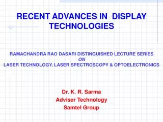
25 10 8 20 6 Gain, dB - CMOS LNA NF, dB - CMOS LNA 4 15 2 0 10 F (GHz) 1 10 100 F (GHz) 1 10 100 CMOS capability- LNA (Gain & NF) State-of-art designs up to 10-20 GHz in CMOS technology have good performances: gain higher than 20 dB, NF lower than 4 dB At higher frequencies the performances start decreasing. Around 77 GHz (W-band) acceptable but non optimal performance are achieved today (gain lower than 20 dB, NF higher than 4 dB)
35 30 25 20 Pout TX, dBm - CMOS PA 15 10 5 0 F (GHz) 1 10 100 1000 CMOS and SiGe capability- PA A. Scavennec et al., IEEE Microwave Mag. 2009
Migration to SOI for better passive integration • In SOI technology the high resistivity of the substrate on which n- and p-MOSFET are created allows dielectric isolation of circuit elements (bulk 20 Ω/cm, SOI > 1000 Ω/cm) • Junction capacitances are reduced increasing maximum operating freq • Reduced noise coupling between digital-analog parts in the same chip • The performances of CPS, CPW or antennas in SOI CMOS are improved due to a reduced amount of energy loss in the supporting substrate
Integrated antenna in CMOS SOI Incidence of substrate resistivity on achievable radiation efficiency and gain F. Gianesello, IEEE SOI 2010
ADC – RADAR requirements • ADC operating at IF: sampling rates up to tens, or even hundreds, of MS/s • ADC sampling at several GS/s available but too power hungry and poor bit resolution Mixer is needed, full-digital RADAR is not convenient • Multi-channel ADC required (e.g. 4 in last LRR automotive Bosch RADAR) • Bit resolution typically higher than 10 b, e.g. a nominal 14b-16 b required for 12 b-14 b ENOB (70 dB dynamic) • Figure of Merit (FoM) in CMOS tech. • from fJ to pJ per conversion-step M. Mishali et al. IEEE Signal Proc. Mag. 2011
Outline of the Talk • Scenarios and applications for highly-integrated low-power RADAR • RADAR architecture, integration levels, RF/mm-Wave transceivers and ADC • Ubiquitous low-power RADAR case studies: E-health (UWB and Doppler) • Automotive (FMCW) • HW-SW implementing platforms for RADAR DSP • Conclusions
Needs for health monitoring • Due to aging population and needs of national health system cost reduction there is high interest in monitoring electronic health devices, specially for heart or respiratory pathologies (CHF, BPCO) • A low-cost RADAR can be used as contactless sensor for monitoring heart rate or breath rate in patient with cardiopulmonary illness or to monitors babies while sleeping against sudden infant death syndrome • Acquired RADAR data are then processed by an home gateway an send to Hospital Information Server
Why RADAR for vital signs sensing • A RADAR senses the mechanical activity of heart or chest instead of the electrical one; from that the heart/breath rate is detected and estimated • The RADAR bio sensor can ensure continuous home monitoring avoiding wires, gels, LOS requirement, electrodes of conventional solutions based on SpO2 measures and multi-lead ECG acquisition (prone to electrode error positioning when done outside hospital ) • Sensor RADAR requirements are low-power and high miniaturization for portability/wearability, short-range, low cost for large volume market CMOS silicon integrated approach should be followed • No ionizing effect
Which RADAR architecture? • Recent proposals based on Ultra Wide Band pulsed RADAR (within 3-10 GHz range) for very low power and low complex short-range (tens of cm) contactless vital sign detection • Correlator-type receiver (Zito, De Rossi, Neri, architecture 2007-2010, implementation in 90 nm CMOS 2011-2012), (Ta-Shun Chu et al., 130 nm CMOS implementation in 2011) • Doppler RADAR based on transmission of un-modulated signal and the analysis of the received echo phase modulated by the chest/heart movement (Dracourt 2004, several works by J. Li, J. Lin et al.). Various designs at 450 MHz, 1.6 GHz, 2.4 GHz, 5.8 GHz in various technologies (250 nm CMOS and BiCMOS, 130 nm CMOS,..)
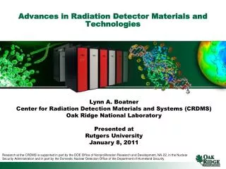
UWB pulsed RADAR • Very low power spectral density (-41.3 dBm/MHz from 3.1 to 10 GHz, 14 bands each of 500 MHz) – ETSI/FCC regulation • Robust against interference, no ionization effect • Transceiver activated when needed (low power) narrowband Narrowband UWB noise
UWB pulsed RADAR • Due to low power the RADAR is limited to detection of heart/breath rate of few Hz, at distances of tens of cm • Single TX/RX antenna multiplexed in time • Transmitter: pulse generator in the TX path transmits short pulses, typ 200-400 ps, towards the human body with fPR > 1 MHz so that the heart can be considered motion-less between consecutive pulses. The energy level of each pulse amounts to few pJ • Low-complex cross correlation receiver architecture Zito et al., IEEE TBCS, 2011
UWB pulsed RADAR • Output signal modulated by the heart movement (RCS of tens of cm2 ) • After a TOF (e.g. few ns for 15-30 cm distance) the signals reflected by the target is captured by the RX antenna • The signal amplified by the LNA is multiplied with a delayed replica of the transmitted pulses generated on-chip by a Shaper circuit • The output signal amplitude is related to the heart position. Vital signs vary within a few Hertz • A 3dB integrator band (Bint) of 100Hz allows an accurate detection Vo (t) at multiplier output Vout (t) at integrator output
Correlation-type Receiver • Averaging several pulses allows increasing SNR (40 dB, 104 pulses) • At the low frequency (DC-100 Hz) of the baseband bio-signal the MOS transistors suffer 1/f flicker noise, higher than thermal noise (KTB term) • To have NFtot~NFLNA 20 dB gain required for the LNA if NF2<15 dB LNA in 90 nm CMOS: 22.7dB gain, 6dB NF, -19dBm ICP1,<35 mW, <0.7 mm2 (6) Fully differential Gilbert cell mul in 90 nm CMOS with NF 14.3 dB, 12 dB gain, 3.7 mW, 0.3 mm2
Transmitter Pulse generator based on triangular pulse generation (TPG) and shaping network (SN): two triangular pulsed (delayed by a pulse period) generated and shaped by a CMOS differential pair
Performance of state of art UWB RADARs • fPR in the range 1-10 MHz, pulses of 300-400 ps and 7-8 pJ energy • BB digital processing can be realized with a simple MCU: low-speed ADC required (12b in ISSCC’11), low data rate serial connection, mainly control tasks to be implemented • Whole chip by Zito et al. in 90 nm CMOS has <2 mm2 area, < 80 mW power consumption, 40dB SNR integrator improvement, <1m range • RADAR packaged in QFN32 and mounted on a test-board including antennas (TX and RX) with 2.3 dBi gain at 3.5 GHz, band 2.8 to 5.4 GHz covering the range of interest from 3 to 5 GHz.
Doppler Bio RADAR • Un-modulated signal transmitted towards the human body, where it is phase modulated by the physiological movement, then reflected and captured by the receiver (h and r are heart and respiratory rate) • Using the same TX signal as RX LO signal, the receiver down-converts the echo signal into BB with no frequency offset. Here it is digitized and the physiological movement can be identified by DSP (FFT or wavelet) C. Li et al., IEEE TIM 2010
Doppler Bio RADAR • DR at 5.8 GHz (1 GHz bandwidth) realized in 130 nm CMOS technology powered by 1.5V batteries with direct conversion quadrature receiver • The LNA has 2.56 dB NF and 24 dB gain; the whole RX chain has min 37 dB gain, -32 dBm P1dB, sensitivity of -101 dBm • The system is sized to ensure 10-20 dB SNR, using a baseband sampling rate of 20 Hz (ADC is sized for 1 kHz) • Off-chip 2x2 patch antennas (separate for TX and RX) were used • With 7 dBm output power detection up to 3 m can be done C. Li et al., IEEE Tran. Micr. Theory Tech. 2010
Automotive RADAR – Why? • Automotive RADARs as core sensor (range, speed) of driver assistance systems: long range (LRR) for Adaptive Cruise Control, medium range (MRR) for cross traffic alert and lane change assist, short-range (SRR) for parking aid, obstacle/pedestrian detection • W.r.t. to other sensing technologies • RADAR is robust in harsh environments • (bad light or weather, extreme temperatures) • Multiple RADAR channels required for • additional angular information • Data fusion in the digital domain with • other on-board sensors
Automotive RADAR –a bit of Story • First tentative for mm-wave automotive RADAR since 70’s but integrated-unfriendly technologies lead to large size, high cost • Since 1998-1999 first generation of RADAR sensors (Daimler, Toyota) • Since 2000 MMIC GaAs-based RADAR in premium cars • Last generation based on 180/130 nm SiGe chipset and advanced packaging with integrated antenna commercially available (e.g. Bosch) • Radar CMOS transceivers recent announced in 65 nm and 90 nm • High RADAR frequency (small λ) allows small size and weight; highly integration with SiGe and future CMOS tech. will reduce assembly and testing costs and hence final user cost much below US$1000 • Market expanding at 40%/year and is expected increasing with all premium/middle cars having a RADAR in next years (7% of all vehicles sold world-wide, mainly in Europe, Japan and US, will have RADARs)
Automotive RADAR – Regulation • 24 GHz and 77 GHz are the dominant bands for automotive • 77-81 GHz is promising since offers 4 GHz bandwidth
Automotive RADAR – 24 vs. 77 GHz • 77 GHz is more challenging for designers: given the same technology the node performances (gain, NF, ..) at 24 GHz are better but 77 GHz RADARs reduce size, volume, weight and hence cost • 77 GHz offers more opportunity for high performance RADAR design: • λ is 3 times smaller (few mm) smaller antenna size for a given beam-width spec and/or better angular separability for the same size • Combination of high transmit power and high bandwidth available at 77 GHz for long range operation and fine distance separability • Due to SiGe and CMOS technologies evolution 77 GHz is affordable • 77-81 GHz (under regulation worldwide) offers 4 GHz Bandwidth with EIRP max PSD of - 3dBm/MHz (-9 dBm/MHz outside the vehicle)
Automotive RADAR – Technical spec RCS pedestrian: 0.3 -0.5 mm2, RCS vehicle: 1-20 m2 (J. Hasch et al., IEEE Tran. Micr Theory Tech, 2012)
Automotive commercial RADARs (J. Hasch et al., IEEE Tran. Micr Theory Tech, 2012) • Product size is in the order of 7 cm per side in LRR, 5 cm per side or lower in MRR and SRR • Products exist with mechanical (slowly, increased size) or electronic beam forming (increased electronic complexity affordable in new tech nodes) • Multi channel transceivers required • All use FMCW RADAR technique
FMCW automotive RADAR principle • Received signal at the ADC (with up and down chirp , two targets are ambiguous; with four chirps two targets can be easily resolved)- LFMCW, FSKCW, MFSCW
FMCW automotive RADAR equations • Receiver power and SNR (min 10 dB required) • Range and relative speed detection from batiment frequency analysis (with FFT in digital domain) The FMCW sweep frequency B and the time sweep determine the achievable range resolution and speed resolution
Automotive RADAR with SiGe mm-Wave T/R • Commercially available from Bosch based on SiGe Infineon Chipset • 2 PCB boards • FCMW modulation • LRR 7dBm Pout, 4 channels (2 TX/RX, 2 RX only), dielectric lens antenna provides high gain for Rmax 250m • Alternative versions with PCB or on-chip Integrated antennas • Power consumption in the order of Watts B. Fleming, IEEE Vehicular Tech. Mag. 2012
Block diagrams of automotive RADAR with SiGe mm-Wave T/R (J. Hasch et al., IEEE Tran. Micr Theory Tech, 2012)
Performance of CMOS transceivers • Today SiGe-based RADAR T/R for commercial automotive RADAR • Tomorrow CMOS-based expected (given technology evolution and trends towards more digital systems)
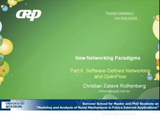
Single and multi beam-forming Analog beam-forming Digital beam-forming To form a beam in a direction, each element of the array is followed by a time delay (phase shifters for narrow band) when all the outputs are summed they add up coherently to form a beam Analog/digital beam-forming Figures from Skolnik book
DOA estimation - Monopulse H. Rohling, Automotive Radar tutorial, 2008 • It needs two beams for each angular coordinate • Sum and difference Δpatterns are used Example, with Gaussian antenna pattern and -3dB beam-width=3o
Outline of the Talk • Scenarios and applications for highly-integrated low-power RADAR • RADAR architecture, integration levels, RF/mm-Wave transceivers and ADC • Ubiquitous low-power RADAR case studies: E-health (UWB and Doppler) • Automotive (FMCW) • HW-SW implementing platforms for RADAR DSP • Conclusions
Implementing platforms for RADAR DSP • Ubiquitous integrated RADAR applications (automotive, bio,..) needs low-power consumption (reduced power supply and thermal issues and increased portability) but can require high computational capabilities and large data transfer rate and memory storage size • Energy-flexibility trade-off to be found between SW-oriented (GPP, DSP, GPU, Microcontroller) and HW-oriented (ASIC, FPGA) platforms R. Whil, IWPC 2011
Custom SoC or MCU for RADAR RADAR is not yet a commodity with accepted/frozen standards • Custom SoC design can provide the best in terms of performance (analog/RF/digital) for a given technology at minimum area and power occupation. Flexibility can be achieved adding in the ASIC also programmable cores • ASIC development time and costs are high rather than designing custom SoC for RADAR in next years an architecture based on MCU+ (DSP/FPGA) is more suited • Thanks to the availability of IP cores such designs can be seen also a prototyping step towards a migration to SoC if and when RADAR becomes a commodity • MCU has low-cost & low-power, on-chip ADC/DAC, but low-performance capabilities (MIPS rather than GOPS, integer operations, low data–rate digital I/O) • For RADAR, MCU suitable for applications needing control of data/operation flow but a co-coprocessor is needed for DSP