Download
1 / 35
350 likes | 473 Views
Front GEM Chambers. Evaristo Cisbani / INFN-Rome Sanità group. Design concepts Foils Mechanics Electronics and DAQ Performance Current activity and plan. Most of the material presented at the SBS meeting in Feb and May/2012. Chamber design Reqs and Guidelines.

E N D
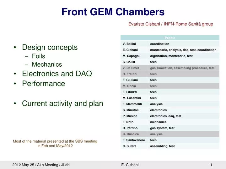
Front GEM Chambers EvaristoCisbani / INFN-Rome Sanità group • Design concepts • Foils • Mechanics • Electronics and DAQ • Performance • Current activity and plan Most of the material presented at the SBS meeting in Feb and May/2012 E. Cisbani
Chamber design Reqs and Guidelines • Hit spatial resolution ~70 mm • Stand large background flux (~250 MHz/cm2g and ~1/1000 charged particles) • Active area 120x40 cm2 • Event acquistion rate ~20 kevt/s • Minimize R&D (follow COMPASS main design) • Reconfigurability (to some extend) • Reuse solutions for SBS rear tracker E. Cisbani
Front Tracker Geometry x(4+4) Back Trackers Geometry SBS Tracker GEM Chambers configuration GEp(5) SBS x6 • Chambers are made of smaller modules • Electronics along the borders and behind the frame (at 90°) – cyan and blue in drawing • Carbon fiber support frame around the chamber (cyan in drawing); dedicated to each chamber configuration E. Cisbani
Foils --- E. Cisbani
Drfit, GEM and Readout foils 20 HV sectors on one side of the GEM 40x50 cm2 • Large GEM module with small dead area • Low material budget/Light Structure • Modular design • Flexible configuration • Balanced weight E. Cisbani
Improvements after first prototype • Protection resistors on the border of the module frame (accessible) • Balance strips capacity (larger strips are now the shortest, smaller are the longest) • Replaced ZIF terminals (from 4 to 2 – more robust, easer to plug) • Thanks to Kondo suggestions: • Added ring of grounding around the readout foil (connected to the front end card GND) • Corrected a trivial (but essential) bug in the readout layers order E. Cisbani
Mechanics Inner Frame Gas Flow Outer Service Frames E. Cisbani
Inner Frame • Permaglas, 8 mm width, 2 or 3 mm thick • 21 slots for protection resistors • 3 Gas In/ 3 Out-lets • 10 Reference holes • Internal spacers (3 vertical 2 horizontal) F. Noto E. Cisbani
Gas Flow / COMSOL MultiPhysics Simulation Final design Flow: 60 cm3/m = 2 Vol/h Pressure drop (Pa): Inlet: 0.0590 Spacers: 0.0015 Module: 0.0462 Outlet: 0.0575 Total: 0.1642 (underestimated) COMSOL/Thin-Film Flow Model Maximize uniformity and steady flux Minimize spacer apertures V. De Smet + F. Noto E. Cisbani
Gas / Current solutions under testing SMC/KR IN or OUT RILSAN pipe Out 13 mm Out 6 mm In 4 mm Glued Permaglas 10 mm «Side» view GEM In 4 mm Top view → No metallic parts Custom and commercial joints Commercial joints are rather large (13 mm!) Pressure drop: 3.16 Pa/m E. Cisbani
Assembling the first 40x50 cm2 module Stretching Stretcher design from LNF / Bencivenni et al. Use stretching and spacers to keep foil flat E. Cisbani Foil Tension: T = 1 kg/cm Spacer Sector: S = 170 cm2 Expected maximum pressure on foil P 10 N/m2 Maximum foil deformation: u 0.0074 * P * S / T = 12 mm Gluing the next frame with spacers
Outer service frame FE cards between frame and backplanes 780 mm 1650 mm • Mechanical support of: • GEM modules • Electronics (PCBs + cables) • Additional services (gas system ...) • Carbon fiber • Long bars made by 3 pieces • Design is in progress • First prototype beginning of summer E. Cisbani F. Noto
Service Frame / Detail Eye bold hole 30x100 mm2 Backplane FE Cards E. Cisbani Reference pin as small mechanical support 23x100 mm2
Material Weight E. Cisbani
Max deformation mm New • Assume 20 kg of payload • Weight applyed in the center of the beam • Two points support E. Cisbani
Electronics and DAQ APV25 Front-End card Backplane MultiPurposeDigitizer (VME module) E. Cisbani
2D Readout Electronics Components GEMFECMPD DAQ 8 mm Up to 10m twisted, shielded copper cable (HDMI) 49.5 mm 75 mm Passive backplane (optional) E. Cisbani • Main features: • Use analog readout APV25 chips • 2 “active” components: Front-End card and VME64x custom module • Copper cables between front-end and VME • Optional backplane (user designed) acting as signal bus, electrical shielding, GND distributor and mechanical support
Readout Electronics / FE v4 Front-end cards: first 25 samples of revision 4 under testing New connector: sligtly different connection scheme (middle spare pins are connected to ground) E. Cisbani Old connectors
Readout Electronics / MPD v4 • Design of v4 under finalization • Move to HDMI type B only • Remove 2 Lemo connectors and USB (more space and firmware resources) • Add piggy back connector for future extension • Trigger sampling at maximum clock speed (240 MHz), time resolution expected at the level of few ns E. Cisbani
(128+12)x25 ns E. Cisbani (2x128+7)x20 ns FEMPD transfer/processing time: ~9 ms/sample APV long analog pipeline (>4 us): use second level trigger Zero suppressed data + VME64x spare readout
DAQ Software Largely rewritten in the past few weeks Bug fixing in progress • Implemented on C++ • Run on Linux • MPD as independent library • One configuration file (text format) • Use open source libconfig++ • Self consistent output binary raw data E. Cisbani • Analysis software: • Based on C++/Root • One geometry configuration file (text) • Ingest raw data and fill a Root tree for further analysis
Some performance Desy – Mainz Test beam E. Cisbani
Beam test @ DESY / Full Module Size 40x50 cm2 Low intensity electron beam 2-6 GeV (few KHz trigger rate) E. Cisbani One 40x50 GEM module One 10x10 GEM chamber An ustrip Si telescope Small scintillators for trigger
Different event patterns We extracted «good events» and measured: Cluster charge, and x-y correlation and ratio Cluster size Noise (RMS) Selection Efficiency Bad event • Standard processing: • Hot channels masking • Common noise suppression (median) • Pedestal subtraction E. Cisbani Good event
Cluster charge, size and noise E. Cisbani Charge distribution and cluster size consistent with COMPASS data We do not expect dramatic difference respect to COMPASS
Charge correlation, beam spot and SNR Pretty good run (011) E. Cisbani ?
Noise (RMS pedestal) vs capacitance Progress since DESY/2010: better grounding, stable firmware Runs differ for different GND connection E. Cisbani
Latest Test under intense beam (Mainz/MAMI)12-16/09/2011 E. Cisbani
Online monitor / Mainz test Low beam current x1 x2 x3 E. Cisbani y2 Event
Online monitor / Mainz test High beam current x1 x2 x3 E. Cisbani y2 Event See Vahe analysis report at SBS meeting
Real Experiment: Olympus, Feb/2012 The APV electronics has been installed on the Olympus 3xGEM tracker made of 6 10x10 chambers with 2D readout (pad/strip – about 2500 chs), operating in a magnetic field at the level of few kG. Two events with opposite magnet polarity; particles bend left o right in the x-histogram (Red triangles show hit candidates) E. Cisbani From Jürgen Diefenbach
Current activity and Plan ---- E. Cisbani
What we have • Electronics: • All readout electronics ordered (order in standby); samples of the latest (final?) FE/backplane version producedLow Voltages and High Voltage power supplies in hands • GEM and readout foils: • About 1/3 ordered, only small part delivered • About another 1/3 funded in 2012 • Mechanics: • All inner frames ordered, about ½ delivered • Outer frame prototype ordered • About 2/3 outer frames funded in 2012 • Gas system: • Mostly funded and procured • Assembling: • Everything ready (or under minor improvement) E. Cisbani
Working on / Open activities • Electronics and DAQ: • production and test • complete firmware implementation / improve software library • optmimize readout performance • (additional user: ATLAS group working on mMeGas prototype) • Mechanics • finalize outer service frame design and produce first prototype • HV • Final decision on HV divider to be taken • Gas • Near chamber configuration to be finalized • GEM modules • assembling and test (as soon as possible) E. Cisbani
Plan • As soon as possible: • When the readout foils will arrive (few days ?) start assembling the first 40x50 module (about 1 module/month-> 0.5 module/week) • latest FE electronics version release for 1 module (on hand) • July-Sept. 2012: • test the module and electronics with rad. source; if fine aks CERN form production • July 2012: • get outer service frame / electronics review at JLab (?) • Sep 2012: • start mass productions of electronics • Dec 2012: • 1st chamber completed (?) • Electronics available, ready for testing • Dec 2013 (+2M): 4 chambers completed (?) E. Cisbani