Download
1 / 60
620 likes | 822 Views
Why Antilock Brakes. Safety Control Stability. History of Antilock Braking Systems. Introduced in 1973 as required by Federal Motor Vehicle Safety Standards, FMVSS 121 Requirement rescinded in 1978 due to lack of relialability.

E N D
Why Antilock Brakes • Safety • Control • Stability
History of Antilock Braking Systems • Introduced in 1973 as required by Federal Motor Vehicle Safety Standards, FMVSS 121 • Requirement rescinded in 1978 due to lack of relialability. • Reintroduced on March 1, 1997 for combination vehicles (tractors and/or trailers). • Reintroduced on March 1, 1998 for single vehicles ( buses and straight trucks over 10,000 pounds GVW).
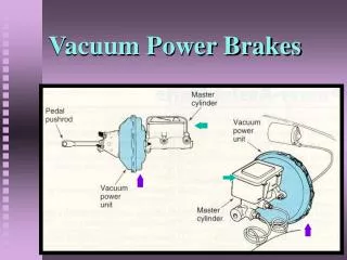
How ABS Works • WABCO ABS is an electronic system that monitors and controls wheel speed during braking.
How ABS Works Continued • ABS monitors wheel speeds at all times and controls braking during wheel lock situations. • Advantage? Improves vehicle stability and control by reducing wheel lock during braking.
How ABS Works Continued • The Electronic Control Unit (ECU) receives and processes input signals from the wheel speed sensors. • When the ECU detects a wheel lockup. • The ECU sends an output signal to the appropriate modulator valve. • Application pressure and wheel speed are controlled.
How ABS Works Continued In the event of a malfunction in the system. The ABS at the effected wheel is disabled. That wheel’s brake returns to a conventional non-ABS brake. The other wheels maintain their ABS controlled braking.
How ABS Works Continued An ABS indicator lamp lets the driver know the status of the system. The lamp is also used to display blink codes for diagnostics.
ABS Configurations • D Version • 4S/4M System • 6S/6M System • 6S/4M system
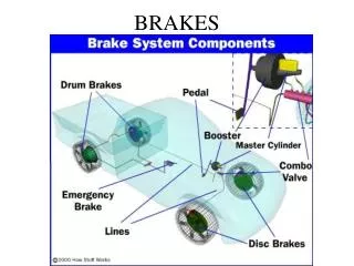
Major components Electronic Control Unit (ECU) Modulator Valves Sensors Wiring harnesses
D Version Cab Mounted ECU • Mounted inside vehicle in clean dry location. • Supports Automatic Traction Control (ATC) • Available in both 12 and 24 volt power
D Version Frame Mounted ECU • Environmentally sealed for frame rail mounting. • Supports Automatic Traction Control (ATC) • Available in both 12 and 24 volt power
Cab Mount Electronic Control Unit Identification Tag • Version type D • Voltage 12 or 24 • Number of sensors 4 • Number of modulator valves 4 • Part number • Serial number
Frame Mount Electronic Control Unit Identification Tag • Version type D • Voltage 12 or 24 • Number of sensors 4 • Number of modulator valves 4 • Part number • Serial number
Electronic Control Unit • Momentarily turns on fault light on start up. • Cycles all valves and relays during start up. • Checks continuity of all sensors during start up. • Stores last sensor output operation in memory. Since sensor operation can not be tested until vehicle is moved, this prevents ABS light from illuminating during start up. • Continuously sends low reference voltage to all components to check for continuity. • Stores active and stored fault codes.
Wheel Speed Sensor • Magnetic pick-up type sensor • Coil wrapped around a magnet • Positioned near the tooth wheel • Motion and magnetism create voltage. • Generates .2 Volt AC at 30 wheel RPM • Same sensor for both 12 and 24 volt system
Wheel Speed Sensor • The wheel speed sensor is a magnetic pick-up type sensor. It consists of a coil wrapped around a magnet. It is positioned near the tooth wheel which is attached to the wheel hub. As the wheel spins, the teeth and spaces between them pass by the sensor. This influences the magnetic flow through the field produced by the magnet. As the magnetic flow builds and collapses with the passing of each tooth and gap, voltage pulses are created in the coil wrapped around the magnet. The pulses are relayed to the electronic control unit and used to determine the relative speed of the wheel.
Wheel Speed Sensor • Sensor produces voltage sine wave. • ECU receives sine wave as an input. • Sine wave is interpreted as binary code and teeth are counted as they pass sensor • Tooth count acceleration and deceleration is interpreted as either normal stopping or impending wheel lock up. • ECU reacts to this information and controls modulator valve and transmission retarder operation.
Tooth Wheels • Located on the wheel hub • 100 teeth per tooth wheel • 80 and 120 tooth wheels for special applications • Up to 5 missing teeth are acceptable without setting a code. • Different types for front and rear wheels • Dirt does not effect sensor operation
Tire Diameter • All tire circumferences must be within 14 percent of each other. • Tire differences greater than 14 percent will set a wheel spin code 5-1through 6
Modulator Valve • Solenoid controlled air valve • Normally open pneumatic design • 12 and 24 volt power supply
Modulator Valves are available in 2 configurations identified by electrical connector types. Open Style Bayonet style
Modulator Valve • Modulator valves operate in 4 modes • Normal (Without Anti-Lock) Brake Application • Exhaust (Anti-Lock Brake Control) • Hold (Anti-Lock Brake Control) • Reapply (Anti-Lock Brake Control)
Modulator ValveNormal Brake Application-Supply • Both supply and exhaust solenoids are inactive. • Air flows unrestricted from the supply port to the delivery port to operate the brake chamber.
Modulator ValveNormal Brake Application-Supply • During normal braking, both solenoids in the ABS modulator valve are de-energized or inactive. The supply diaphragm control chamber of the inlet valve is open to the atmosphere. Air pressure entering the supply port unseats the supply diaphragm. This opens the passage to the delivery port and allows air pressure to flow directly through the valve and into the brake chamber. • Simultaneously, air pressure flows past the de-energized exhaust solenoid and puts pressure on the exhaust diaphragm. This pressure combines with spring force to keep the exhaust diaphragm seated and close the path from the delivery port to the exhaust port. • The ABS valve maintains this balanced (or pressure increase) position until a wheel starts to lock. Then one or both of the solenoids are activated by the ECU.
Modulator ValveAnti-Lock Brake Control-Decrease • Supply solenoid is energized stopping air flow into the valve. • The exhaust Solenoid is energized opening the exhaust port and reducing the air pressure within the brake chamber.
Modulator ValveAnti-Lock Brake Control-Decrease • When the ECU determines that a wheel is going to lock, it first energizes (activates) both ABS valve solenoids. The energized supply solenoid allows air pressure to enter the supply diaphragm control chamber, where it holds the supply diaphragm in the seated position. This stops any more air from entering the brake chamber. • When energized, the exhaust solenoid cuts off the supply of air pressure entering the exhaust diaphragm and exhausts that air to the atmosphere. Thus pressure from the brake chamber enters through the delivery port and unseats the exhaust diaphragm. This opens the passage between the delivery port and exhaust port, which releases air pressure from the brake chamber.
Modulator ValveAnti-Lock Brake Control-Hold • Supply solenoid remains energized preventing supply air pressure from entering the supply port. • Exhaust solenoid is de-energized, closing the exhaust port, maintaining brake chamber pressure.
Modulator ValveAnti-Lock Brake Control-Hold • When enough air pressure is released through the exhaust port to stop the wheel from locking, the exhaust solenoid is de-energized. This seats the exhaust diaphragm .and stops any more air from leaving the brake chamber. The supply solenoid remains energized to prevent air pressure from passing through the ABS valve. The remaining air pressure in the brake chamber is held and remains constant.
Modulator ValveAnti-Lock Brake Control-Reapply • Both supply and exhaust solenoids are de-energized. • Supply air pressure flows unrestricted from the delivery line to the brake chamber to reapply the brake.
Modulator ValveAnti-Lock Brake Control-Reapply • To achieve proper braking , The ECU monitors wheel speed and determines when to reapply brake pressure. When necessary, both ABS solenoids are de-energized, returning the system to the normal brake-application supply state. • The ECU cycles through the different valve states (pressure increase, pressure decrease, and pressure hold)very rapidly to control wheel speed. The ABS system achieves efficient braking by independent controlling individual wheels.
Modulator ValveAnti-Lock Brake Control-Release • Pressurized air from the delivery port and brake chamber flow back into the valve and our the supply port. • A small amount of air flows out the exhaust valve.
Modulator ValveAnti-Lock Brake Control-Release • Air pressure at the supply port decreases when the brake pedal valve is released. This reverses the direction of the airflow through the valve and exhausts air pressure from the brake chamber. • Air pressure is also released from the ABS valve exhaust port during brake release.
Fault Codes • Stored fault • Active fault
Active Fault • Example of active code below fault in right rear drive axle modulator valve.
Stored Codes • Sensor signal erratic, left front axle and too much sensor gap left rear drive axle.
System O.K. • Blink code flashes 1 pause 1
Clearing Fault Codes, Defect Corrected • Hold blink code button for 3 seconds. • Blink code flashes 8 quick blinks indicating memory cleared if defect is repaired. • Blink code flashes 2 repeatedly indicating system configuration. • 1 Blink = 6S/6M 2 Blinks = 4S/4M 4 Blinks =6S/4M • Cycle ignition switch, ABS light remains lit until vehicle is driven 4 MPH or a wheel speed of 30 RPM.
Trouble Shooting Techniques • Electrical Troubleshooting • Diagnosing Modulator Valves • Diagnosing Speed Sensors • Sensor and Modulator Valve Location • Data-Link
Electrical troubleshooting Techniques • Three step troubleshooting techniques • Unit Test • Ground Test • End to End Test
Unit Test • This test will determine if a component is defective, wiring is broken or corrosion is present. • Total circuit resistance is measured to determine if component and wiring are in satisfactory condition. • Perform test using a multimeter to check for correct ohm reading. • Low resistance indicates shorted wires or coils. • High resistance indicates corrosion, broken wires or corroded connections.
Ground Test • This test will determine if a direct electrical short to ground exists. • Harness is disconnected from control unit while component is left connected to harness. • Perform test using a multimeter with the negative lead connected to the chassis ground. • Probe all electrical connector sockets or pins and determine is continuity between wires and ground exists. • Continuity present indicates direct short to ground.
End to End Test • This test will determine if a defect exists within the wiring harness. • Harness is disconnected from component and control unit. • Perform test using a multimeter to check for continuity between wires in harness. • Probe all electrical connector wiring sockets or pins beginning with pin #1 or A • Continuity between wires indicates short circuit.
12 volt solenoid test Verify 4 to 9 ohms Test inlet solenoid coil from contact #1 and #2, normal ohm reading should be 5.6 ohms. Test exhaust solenoid coil from contact #1 and #3, normal ohm reading should be 5.6 ohms. 24 volt solenoid test Verify 11 to 21 ohms Test inlet solenoid coil from contact #1 and #2, Normal ohm reading should be 14.7 ohms. Test exhaust solenoid coil from contact #1 and #3, normal ohm reading should be 14.7 Ohms. Modulator Valve Diagnostics Ohm Test