Download
1 / 1
60 likes | 317 Views
System Diagram of a Boxford MT2 CNC Machine. -Z. G&M Code Program. Control Panel MDI (Manual Data Input) Feedrate Override Homing Switches. -X. Spindle. Visual Display (feedback to Monitor screen). Machine Control Unit. External Input Devices. External Output Devices.

E N D
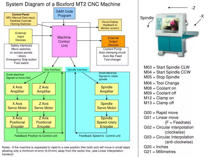
System Diagram of a Boxford MT2 CNC Machine -Z G&M Code Program Control Panel MDI (Manual Data Input) Feedrate Override Homing Switches -X Spindle Visual Display (feedback to Monitor screen) Machine Control Unit External Input Devices External Output Devices Safety interlocks Micro switches on access panels / doors Emergency Stop button Foot switch Coolant Pump Auto clamping chuck Auto Bar Feed Tool changer M03 = Start Spindle CLW M04 = Start Spindle CCW M05 = Stop Spindle M06 = Tool Change M08 = Coolant on M09 = Coolant off M12 = Clamp on M13 = Clamp off G00 = Rapid move G01 = Linear move (F = Feedrate) G02 = Circular interpolation (clockwise) G03 = Circular Interpolation (anti-clockwise) G20 = Inches G21 = Millimetres Axis Interface Spindle Interface Small electrical Signals to rotate spindle Small electrical Signals to move X&Z X Axis Amplifier Spindle Amplifier Z Axis Amplifier X Axis Servo Motor Z Axis Servo Motor Spindle Servo Motor X Axis Positional Encoder Z Axis Positional Encoder Spindle Speed rotary Encoder Feedback Position to Control unit Feedback Speed to Control unit Notes:- If the machine is requested to rapid to a new position then both axis will move in small steps allowing only a minimum of error (0.01mm) away from the vector line. (see Linear Interpolation handout)