Download
1 / 36
360 likes | 446 Views
The Interaction of the Atmosphere and Geodetic GPS. Arthur Niell Haystack Observatory, MIT. Outline. Geodesy, the atmosphere, and GPS A simple model Model limitations System errors Recommendations. Goals. Develop a model for understanding measurements and uncertainties

E N D
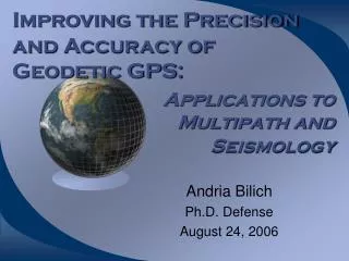
The Interaction of the Atmosphere and Geodetic GPS Arthur Niell Haystack Observatory, MIT ICC
Outline • Geodesy, the atmosphere, and GPS • A simple model • Model limitations • System errors • Recommendations ICC
Goals • Develop a model for understanding measurements and uncertainties • Illustrate the interaction of observation limitations and derived results ICC
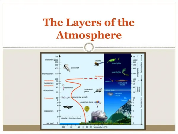
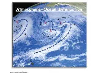
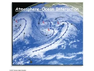
Geodesy and Meteorology • Geodesy - measuring the shape of the earth and its orientation in space • Traditional - direct measurement • Space-based - indirect measurement • GPS, VLBI, and SLR • All affected by refraction in the atmosphere • Meteorology • Refractivity is information ICC
Basis of Measurement • Determine distances by measuring time delays and dividing by speed of light • Solve ‘simple’ geometry problem • Problem: speed of light is affected by atmosphere ICC
Famous Phrase One person’s noise is another person’s signal (Atmosphere refraction is noise for the geodesist, but it is important information for the meteorologist.) ICC
Space-based Geodesy (1) • Global Positioning System (GPS) • 24-27 satellites in 12 hour orbits • Transmits time-coded signals at two radio frequencies • Passive receivers measure range to satellites • Global array of receivers used to determine orbits of satellites, positions of receiving antennas, and delay of signal by the atmosphere ICC
Space-based Geodesy (2) • Very Long Baseline Interferometry (VLBI) • Extra-galactic radio sources (galaxies and quasars) are the source of radio signals • Received at two frequencies by large radio telescopes • Delay of arrival between telescopes used to calculate source positions, antenna positions, and atmosphere delay estimates. • EGRS provide celestial reference frame ICC
Space-based Geodesy (3) • Satellite Laser Ranging (SLR) • 2 satellites with optical reflectors • Laser ranging to satellites from ground stations • Round-trip light travel time used to determine orbits of satellites and positions of laser systems • Atmosphere small effect ICC
Simple model for GPS • Single receiving antenna • Orbits perfectly known • Estimate • Antenna position • Neutral atmosphere delay • zenith delay • gradient • Receiver clock offset ICC
Accuracy goal • Site position • Horizontal - 1 mm • Vertical - 3 mm • Atmosphere delay • Zenith - 6 mm • Gradient - ? ICC
Some equations • Receiver knows transmitted time, ti, and received time, tr, for each satellite, so observed delay is i = tr - ti • This is composed of geometric delay, atmosphere delay, and receiver clock error i = gi + atm,i + ci ICC
Observations • Geometric delay to each satellite contains three unknowns: latitude, longitude, and distance of the antenna from center of the Earth • Atmosphere delay to each satellite is different • Clock error is the same for all satellites observed at the same time • ==> 5 unknowns for first satellite 1 more for each additional one ICC
Some more equations • To have a solution must assume: • atmosphere delay is given by one parameter • delay to each satellite can be calculated based on its position • e.g. for plane parallel atmosphere atm = atm(90o)/sin(elev) or, more generally atm,i = atm(90o)*m(elevi) ICC
Observable • Subtract apriori delay based on approximate position i = i - g0,i = (gi - g0,I) + atmZ *m(elevi) + c • Convert to local N, E, U coordinates ICC
THE Equation(no gradients) ci = -[ e*sin(i)cos(i) + n*cos(i)cos(i) + u*sin(i)] + atmZ *m(i) + c • 5 unknowns => • at each epoch observe 5 satellites ICC
How to use THE equation • Assume measurements are perfect except for effect to be investigated • Generate fake residuals for observaton directions of typical or ideal GPS constellation and site location • Estimate position, atmosphere, and clock parameters from least-squares solution to observations and model ICC
Sources of Error • Inaccuracy of the models • Error in measurements • system noise • multipath/scattering • Examples • Mapping function error (model) • Scattering/multipath (system error) • Gradients (system + observations) ICC
Example - 1 • Using wrong mapping function • Generate residuals using wet MF • Estimate solution using hydrostatic MF • Input • Zenith wet delay 20 mm • 8 elevations from 5° to 80° • Azimuthal symmetry assumed ICC
Example - 1 • Solution (units are mm) parameter input estimate E 0.0 0.3 N 0.0 -0.6 U 0.0 -4.6 ZWD 20.0 21.8 clock 0.0 -6.0 (post-fit residuals < 1 mm) ICC
Example - 1 • Height error ~ 1/3 of delay error at lowest elevation • ZWD error ~ -0.4 * height error • Clock error compensates for height error ICC
Example - 2 • Scattering/multipath phase errors • Observations obtained from averaged post-fit residuals for WES2 • Estimate solution using wet mapping function • Input • Zenith wet delay 0 mm • 8 observations from 5° to 80° • 8 observations from 15° to 80° ICC
Example - 2 • Solution (units are mm) parameter input 5° soln 15° soln E 0.0 0.0 0.0 N 0.0 3.9 1.2 U 0.0 -2.0 -15.2 ZWD 0.0 -0.6 4.2 clock 0.0 -0.8 -17.1 RMS 1.9 1.1 ICC
Real data ICC
Accuracy • Which minimum elevation gives most correct value for ZWD? • Compare ZWD by GPS with WVR, radiosonde, and VLBI • Two weeks of data in 1995 August • Corrections to radiosonde for dry bias • Correction to WVR for refractivity definition ICC
Points of Comparison • Best GPS agreement is for inclusion of low elevation data • VLBI independent of minimum elevation • Not shown in this figure • VLBI and GPS scales agree to ~2% • WVR scale 5% above GPS/VLBI • radiosonde scale 5% below GPS/VLBI ICC
Accuracy vs Precision • What minimum elevation should be used in data analysis? • Accuracy better using low elevations • Formal errors decrease with lower elevations • Scatter increases with lower elevations • Atmosphere errors larger • Multipath error larger ICC
Points to make • Elevation-dependent errors affect height and ZWD: correlation -0.4 • Antenna/multipath problems cause: • minimum-elevation dependent biases to height and to ZWD • time-dependent errors as constellation changes • Asymmetry of az-el for GPS interacts with gradients to give both vertical and horizontal errors ICC
Recommendations • Evaluate lowest elevation that can be used based on known error sources • Perform elevation cutoff tests to determine severity of systematic errors • Look at post-fit residuals • detect systematic errors • find potentially troublesome sites. ICC
Summary • Hydrostatic mapping function error is more important than wet except near the equator. • Use of NWM improves hydrostatic mapping function significantly. • Application to VLBI data indicates that other modeling errors comparable. • Wet mapping function improvement is much less than hydrostatic. ICC