Download
1 / 31
310 likes | 320 Views
Framing and Encoding EECS 122: Lecture 26. Department of Electrical Engineering and Computer Sciences University of California Berkeley. Last Time. We assumed that the link carries frames Error detecting code part contains bits that add redundancy Natural Questions:

E N D
Framing and EncodingEECS 122: Lecture 26 Department of Electrical Engineering and Computer Sciences University of California Berkeley
Last Time • We assumed that the link carries frames • Error detecting code part contains bits that add redundancy • Natural Questions: • How do physical media transport the frames? • Why are some links faster than others? • What limits the amount of information we can send on a link? Payload FH EDC k bits n bits A. Parekh, EE122 S2003. Revised and enhanced F'02 Lectures
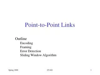
Today • Link Functions and Components • The role of Noise and Bandwidth in determining link rate • Encoding: Converting bits to analog signals • Physical Layer Function • Framing: Establishing the conventions that denote boundaries • Data Link Layer Function A. Parekh, EE122 S2003. Revised and enhanced F'02 Lectures
Link Functions • Functions • Construct Frame with Error Detection Code • Encode bit sequence into analog signal • Transmit bit sequence on a physical medium (Modulation) • Receive analog signal • Convert Analog Signal to Bit Sequence • Recover errors through error correction and/or ARQ Signal Adaptor Adaptor Adaptor: convert bits into physical signal and physical signal back into bits A. Parekh, EE122 S2003. Revised and enhanced F'02 Lectures
Link Components NRZI A. Parekh, EE122 S2003. Revised and enhanced F'02 Lectures
Link Properties • Function • Duplex/Half Duplex • One stream, multiple streams • Characteristics • Bit Error Rate • Data Rate (this sometimes mistakenly called bandwidth!) • Degradation with distance • Cables and Fibers • CAT 5 twisted pair: 10-100Mbps, 100m • Coax: 10-100Mbps, 200-500m • Multimode Fiber: 100Mbps, 2km • Single Mode Fiber: 100-2400Mbps, 40km • Wireless A. Parekh, EE122 S2003. Revised and enhanced F'02 Lectures
Example: Optical Links A. Parekh, EE122 S2003. Revised and enhanced F'02 Lectures
Link rate and Distance Links become slower with distance because of attenuation of the signal Amplifiers and repeaters can help A. Parekh, EE122 S2003. Revised and enhanced F'02 Lectures
Noise • A signal s(t) sent over a link is generally • Distorted by the physical nature of the medium • This distortion may be known and reversible at the receiver • Affected by random physical effects • Shot noise • Fading • Multipath Effects • Also interference from other links • Wireless • Crosstalk • Dealing with noise is what communications engineers do A. Parekh, EE122 S2003. Revised and enhanced F'02 Lectures
Noise limits the link rate • Suppose there were no noise • E.g. Send s(t) always receive s(t+Δ) • Take a message of N bits say b1b2….bN, and send a pulse of amplitude of size 0.b1b2….bN • Can send at an arbitrarily high rate • This is true even if the link distorts the signal but in a known way • In practice the signal always gets distorted in an unpredictable (random) way • Receiver tries to estimate the effects but this lowers the effective rate • One way to mitigate noise is to jack up the power of the signal • Signal to Noise ratio (SNR) measures the extent of the distortion effects A. Parekh, EE122 S2003. Revised and enhanced F'02 Lectures
Bandwidth affects the data rate • There is usually a fixed range of frequencies at which the analog wave can traverse a link • The physical characteristics of the link might govern this • Example: • Voice Grade Telephone line 300Hz – 3300Hz • The bandwidth is 3000Hz • For the same SNR, a higher bandwidth gives a higher rate A. Parekh, EE122 S2003. Revised and enhanced F'02 Lectures
Sampling Result (Nyquist) • Suppose a signal s(t) has a bandwidth B. • Sampling Result: Suppose we sample it (accurately) every T seconds. • If T≤ 1/2B then it is possible to reconstruct the s(t) correctly • Only one signal with bandwidth B has these sample points • There are multiple signals with these sample points for signals with bandwidth greater than B • Increasing the bandwidth results in a richer signal space • No noise allowed in the sampling result A. Parekh, EE122 S2003. Revised and enhanced F'02 Lectures
Sampling Continued • But now assume noise that is distributed uniformly over the frequency band. • Then the richer signal space will enable more information to be transmitted in the same amount of time. • Higher bandwidth Higher rate (for the same SNR) A. Parekh, EE122 S2003. Revised and enhanced F'02 Lectures
The Frequency Spectrum is crowded… A. Parekh, EE122 S2003. Revised and enhanced F'02 Lectures
Fundamental Result • The affect of noise on the data is modeled probabilistically. • It turns out that there is a maximum possible reliable rate for most channels called the capacity C: • There is a scheme to transmit at C with almost no errors • Finding this scheme is tricky but it exists • For a commonly observed kind of noise called Additive White Gaussian Noise (AWGN) the capacity is given by: • C = Wlog2(1 + S/N) bits/sec (Shannon) • Example: Voice grade line: S/N = 1000, W=3000, C=30Kbps • Technology has improved S/N and W to yield higher speeds such as 56Kb/s A. Parekh, EE122 S2003. Revised and enhanced F'02 Lectures
Encoding • Goal: send bits from one node to another node on the same physical media • This service is provided by the physical layer • Problem: specify a robust and efficient encoding scheme to achieve this goal A. Parekh, EE122 S2003. Revised and enhanced F'02 Lectures
Assumptions • We use two discrete signals, high and low, to encode 0 and 1 • The transmission is synchronous, i.e., there is a clock used to sample the signal • In general, the duration of one bit is equal to one or two clock ticks • If the amplitude and duration of the signals is large enough, the receiver can do a reasonable job of looking at the distorted signal and estimating what was sent. A. Parekh, EE122 S2003. Revised and enhanced F'02 Lectures
NRZ (non-return to zero) Non-Return to Zero (NRZ) • 1 high signal; 0 low signal • Disadvantages: when there is a long sequence of 1’s or 0’s • Sensitive to clock skew, i.e., difficult to do clock recovery • Difficult to interpret 0’s and 1’s (baseline wander) 0 0 1 0 1 0 1 1 0 Clock A. Parekh, EE122 S2003. Revised and enhanced F'02 Lectures
NRZI (non-return to zero intverted) Non-Return to Zero Inverted (NRZI) • 1 make transition; 0 stay at the same level • Solve previous problems for long sequences of 1’s, but not for 0’s 0 0 1 0 1 0 1 1 0 Clock A. Parekh, EE122 S2003. Revised and enhanced F'02 Lectures
Manchester Manchester • 1 high-to-low transition; 0 low-to-high transition • Addresses clock recovery and baseline wander problems • Disadvantage: needs a clock that is twice as fast as the transmission rate • Efficiency of 50% 0 0 1 0 1 0 1 1 0 Clock A. Parekh, EE122 S2003. Revised and enhanced F'02 Lectures
4-bit/5-bit (100Mb/s Ethernet) • Goal: address inefficiency of Manchester encoding, while avoiding long periods of low signals • Solution: • Use 5 bits to encode every sequence of four bits such that no 5 bit code has more than one leading 0 and two trailing 0’s • Use NRZI to encode the 5 bit codes • Efficiency is 80% 4-bit 5-bit 4-bit 5-bit • 1000 10010 • 1001 10011 • 1010 10110 • 1011 10111 • 1100 11010 • 1101 11011 • 1110 11100 • 1111 11101 • 0000 11110 • 0001 01001 • 0010 10100 • 0011 10101 • 0100 01010 • 0101 01011 • 0110 01110 • 0111 01111 A. Parekh, EE122 S2003. Revised and enhanced F'02 Lectures
Modulation • The function of transmitting the encoded signal over a link, often by combining it with another (carrier signal) • E.g. Frequency Modulation (FM) • Combine the signal with a carrier signal in such a way that the instantaneous frequency of the received signal contains the information of the carrier • E.g. Frequency Hopping (OFDM) • Signal transmitted over multiple frequencies • Sequence of frequencies is pseudo random A. Parekh, EE122 S2003. Revised and enhanced F'02 Lectures
Framing • Goal: send a block of bits (frames) between nodes connected on the same physical media • This service is provided by the data link layer • Use a special byte (bit sequence) to mark the beginning (and the end) of the frame • Problem: what happens if this sequence appears in the data payload? A. Parekh, EE122 S2003. Revised and enhanced F'02 Lectures
Byte-Oriented Protocols: Sentinel Approach 8 8 • STX – start of text • ETX – end of text • Problem: what if ETX appears in the data portion of the frame? • Solution • If ETX appears in the data, introduce a special character DLE (Data Link Escape) before it • If DLE appears in the text, introduce another DLE character before it • Protocol examples • BISYNC, PPP, DDCMP STX Text (Data) ETX A. Parekh, EE122 S2003. Revised and enhanced F'02 Lectures
Byte-Oriented Protocols: Byte Counting Approach • Sender: insert the length of the data (in bytes) at the beginning of the frame, i.e., in the frame header • Receiver: extract this length and decrement it every time a byte is read. When this counter becomes zero, we are done A. Parekh, EE122 S2003. Revised and enhanced F'02 Lectures
Bit-Oriented Protocols 8 8 • Both start and end sequence can be the same • E.g., 01111110 in HDLC (High-level Data Link Protocol) • Sender: inserts a 0 after five consecutive 1s • Receiver: when it sees five 1s makes decision on the next two bits • if next bit 0 (this is a stuffed bit), remove it • if next bit 1, look at the next bit • If 0 this is end-of-frame (receiver has seen 01111110) • If 1 this is an error, discard the frame (receiver has seen 01111111) Start sequence End sequence Text (Data) A. Parekh, EE122 S2003. Revised and enhanced F'02 Lectures
Clock-Based Framing (SONET) • SONET (Synchronous Optical NETwork) • Developed to transmit data over optical links • Example: SONET ST-1: 51.84 Mbps • Many streams on one link • SONET maintains clock synchronization across several adjacent links to form a path • This makes the format and scheme very complicated A. Parekh, EE122 S2003. Revised and enhanced F'02 Lectures
SONET Multiplexing • STS-3c has the payloads of three STS-1’s byte-wise interleaved. • STS-3 is a SONET link w/o multiplexing • For STS-N, frame size is always 125 microsec • STS-1 frame is 810 bytes • STS-3 frame is 810x3 =2430 bytes FH STS-1 FH STS-1 FH STS-3c FH STS-1 A. Parekh, EE122 S2003. Revised and enhanced F'02 Lectures
STS-1 Frame • First two bytes of each frame contain a special bit pattern that allows to determine where the frame starts • No bit-stuffing is used • Receiver looks for the special bit pattern every 810 bytes • Size of frame = 9x90 = 810 bytes Data (payload) overhead SONET STS-1 Frame 9 rows 90 columns A. Parekh, EE122 S2003. Revised and enhanced F'02 Lectures
Clock-Based Framing (SONET) • Details: • Overhead bytes are encoded using NRZ • To avoid long sequences of 0’s or 1’s the payload is XOR-ed with a special 127-bit patter with many transitions from 1 to 0 A. Parekh, EE122 S2003. Revised and enhanced F'02 Lectures
Summary • Links are subject to random noise • For a given probabilistic model of the noise it may be possible to compute its capacity • Generally depends on SNR and Bandwidth • Encoding – specifies how bits are represented on in the analog signal • Challenge – achieve: • Efficiency – ideally, bit rate = clock rate • Robust – avoid de-synchronization between sender and receiver when there is a large sequence of 1’s or 0’s • Framing – specify how blocks of data are transmitted • Challenge • Decide when a frame starts/ends • Differentiate between the true frame delimiters and delimiters appearing in the payload data A. Parekh, EE122 S2003. Revised and enhanced F'02 Lectures